- Civil Lab Mechanical Lab Engineering Lab Equipments
- sales@didacticlabequipments.com

CAT NO: DIDACTICNTE-11-12-0052
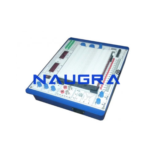
Electronics Circuit Trainer.
Base unit
FEATURES
High level, high quality digital-analog trainer
Includes Two Digital Meters one for 20V Voltmeter and other for 200mA Ammeter
Combines all essential functions of analog and
digital experiment with removable breadboard,
Includes DC power supply function generator, two pulse switches, 8 ohm 0.25W speaker etc.
SPECIFICATIONS
Solder-less,breadboard
Interconnected with tie points Nickel plated contact, fitted with all DIP sizes and all components with lead and solid wire. It can be changed and replaced for different purposes and can be connected with demonstration panel. Therefore, it is very convenient for both teachers and students
DC power supply
Fixed DC Output : ±5V, ±12V @ 500Ma
Variable DC Output : Dual 0~30V, 0~ -30V @ 500mA
AC power supply : 0~5~0 VAC,12~0~12VAC
Potentiometers: :1Kohm,10Kohm
Function generator
Frequency range : 1Hz ~ 10Hz
: 10Hz ~ 100Hz
: 100Hz ~ 1KHz
: 1 KHz ~ 10 KHz
: 10 KHz ~ 100 KHz
Amplitude
Sine wave output : 0 ~ 6 Vpp variable @ 1Hz~100Hz in 5 steps
Triangle wave output : 0 ~ 6 Vpp variable @ 1Hz~ 300KHz in 5 steps
Square wave output : 0 ~ 5 Vpp variable @ 1Hz~400KHz in 5 steps
TTL mode output : 5V@1Hz~1MHz in 5 steps
Two digits of 7 segment LED display
One pulse switch
Push buttons to generate inverting and non inverting pulses supported with de-bounce elimination
Data switches
Toggle switches and corresponding output point. When switch is set at “Down” position, the output is LOW level, contrarily it is to be 'High' level while setting at “Up” position
Speaker
8ohm/0.5W to be used for load
Four channel adaptor
The two banana sockets and BNC jacks suitable for the trainer to be connected with peripherals
Sixteen bit LED display
Red LEDs separate input terminals. The LED will be lighted up when input is at “High level ”and it will be turned OFF when it is at “No Input” or at “Low level”
Packing list
• Instruction manual hard copy and Soft Copy In CD.
• Power supply mains 3 pin cord
• Patch cords
FOLLOWING MODULES WILL BE PROVIDED WITH ANALOG & DIGITAL LAB TRAINER
Topics of Experiments :
1. Rectifier and Filter Circuits module
2. Characteristics of diode , zener diodes and leds
3. Power supply circuit modules
4. Junction Transistors characteristics modules
Common Emitter Amplifier Characteristics
5. Diode wave shaping circuit
6. Transistor baising
7. Load lines ac transistor response study
8. Zener diode as voltage regulator
9. Fet characteristics
10. Voltage multiplier circuits
