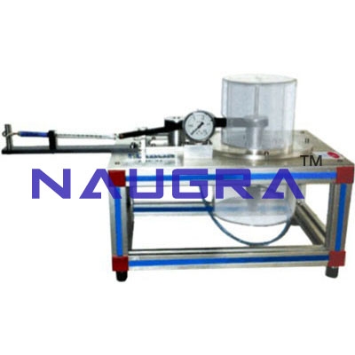
Computer Controlled Radial Flow Turbine- EngineeringTraining Systems Lab
EXERCISES AND PRACTICAL POSSIBILITIES Some Practical Possibilities of the Unit...
Fluid Mechanics manufactured in India for global tender supply. Didactic Lab Equipments is a leading Fluid Mechanics manufacturer, exporter and bulk supplier, serving Ministry of Education tenders, TVET institutes, polytechnics and engineering colleges across 100+ countries with factory-direct pricing.
Our fluid mechanics meet international quality standards and ship with technical documentation, installation support, training materials and a manufacturer warranty. We accept LC, T/T and MOE tender payment terms for schools, colleges, polytechnics and vocational training centres worldwide.
EXERCISES AND PRACTICAL POSSIBILITIES Some Practical Possibilities of the Unit...
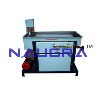
Technical Description The hydrodynamic trainer permits basic experiments on fluid mechanics....
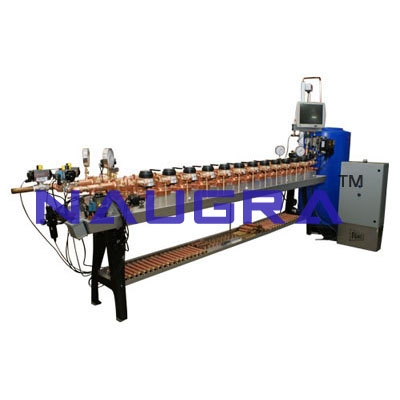
Technical Description A common problem in the installation of pipe-work is the determination of pressure and flow rate in complex pipe systems....
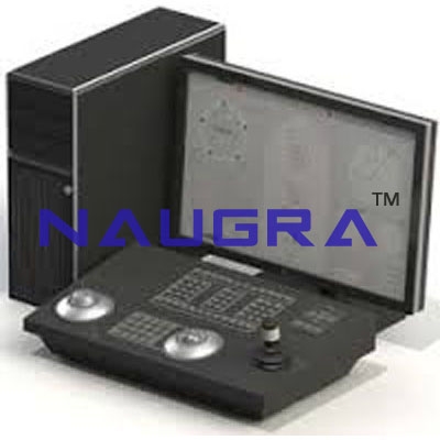
Technical Description The trainer permits basic experiments on fluid mechanics....
Technical Description With this well equipped hydrostatics bench, numerous experiments on the topic of the hydrostatics of liquids and gases can be carried out....
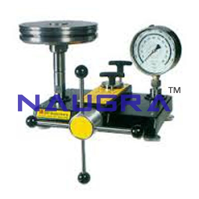
Technical Description The benchtop unit contains a Bourdon tube manometer as the test object and a piston manometer for generating the test pressure...
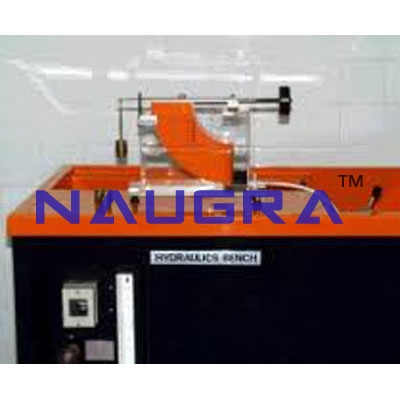
Technical Description The apparatus comprises a transparent measuring container that is filled with water for the experiments....
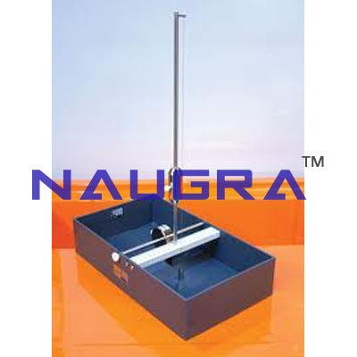
Technical Description This simple apparatus for determining the metacentre of a model hull is particularly suitable for experiments in small groups....
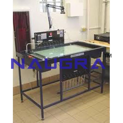
Technical Description On the unit, the behaviour of two dimensional flows can be investigated....
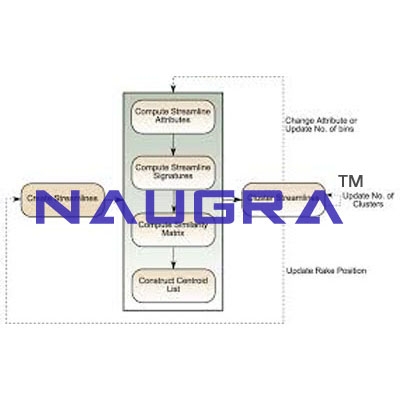
Technical Description The unit is used for the qualitative depiction of flow lines in flowing water....
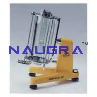
Technical Description Using the unit, the dynamic viscosity of a liquid can be determined....
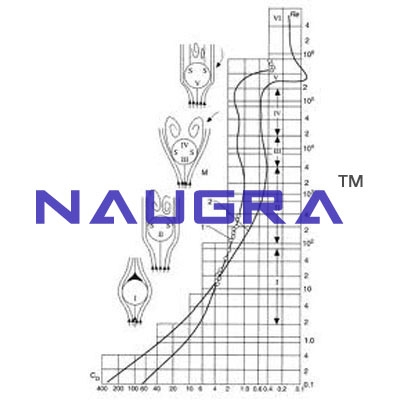
Technical Description Two Plexiglass cylinders are provided for performing the experiment, these are filled with fluids of varying viscosity....
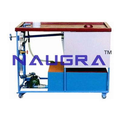
Hydraulics Bench Technical Description - The allows to carry out a large number of flow-related experiments....
Technical Description The base module forms the basis for a wide range of experiments on fluid mechanics....
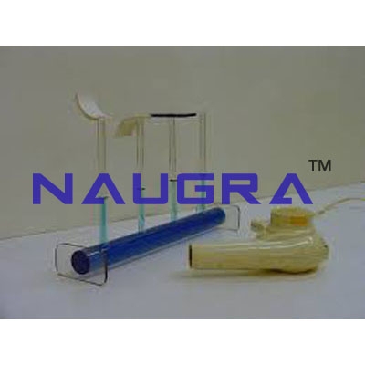
Technical Description The entire experimental set-up is clearly laid out on a metal panel, this is fitted to the Basic Hydraulics Bench....
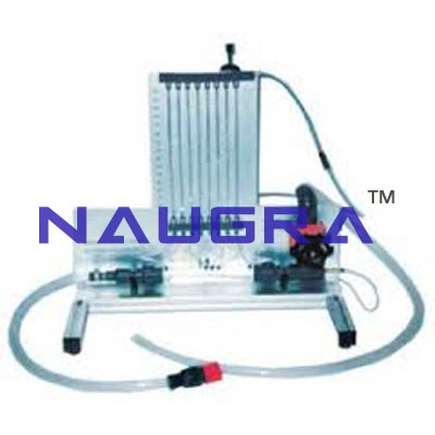
Technical Description The demonstrator is designed such that it can be set up with an inlet tank and an outlet tank...
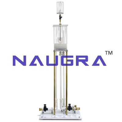
Technical Description The core of the demonstrator is a transparent pipe section (di=10mm, length 540mm) with a streamlined inlet through which water flows....
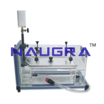
Technical Description The experimental pipe section in this unit is horizontal, in contrast to the vertical pipe...
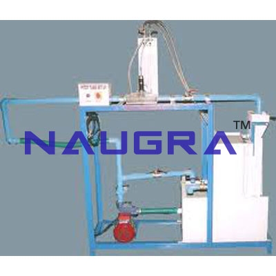
Technical Description It is possible to move the Pitot-static tube across the entire cross-section of the pipe and thus measure the pressure profile....
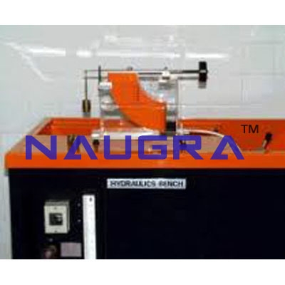
Technical Description During the experiments on various drag bodies, ink is injected through fine nozzles into a horizontal flow chamber....
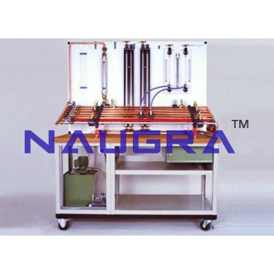
Technical Description The experimental set-up can be used on its own or with the Basic Hydraulics Bench....
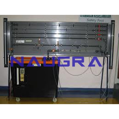
Technical Description The panel comprises a pipe network with sub-sections that can be isolated individually and one measurement section in which different elements can be inserted....
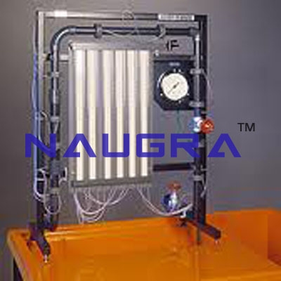
Technical Description The unit is used for the investigation of pressure losses in bends,...
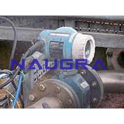
Technical Description The Flow Meter Demonstration Apparatus contains different flow rate measurement devices that are clearly laid out with the associated pipework on a metal sheet....
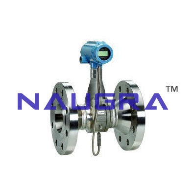
Technical Description The is used for experiments on various methods of measuring volumetric and mass flow rates....
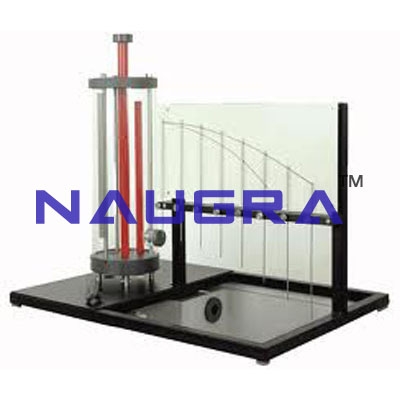
Technical Description A plexiglas cylinder is equipped with an adjustable overflow and scale which enables the height of the water column to be set and read accurately....
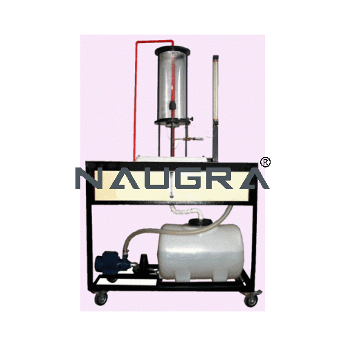
Technical Description The water drains vertically from a transparent supply tank through a nozzle due to the hydrostatic pressure....
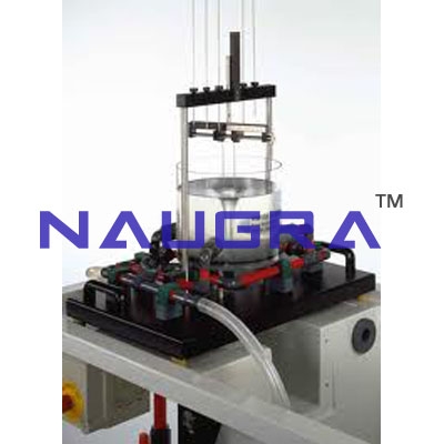
Technical Description The unit is suitable for investigating natural and forced vortices that are generated in a transparent tank....
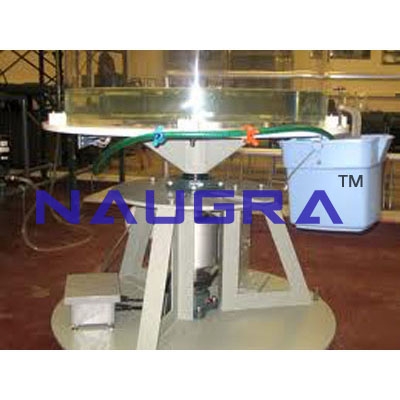
Technical Description Using this unit both natural and forced vortices can be generated and observed. A forced vortex forms when the entire tank is rotated....
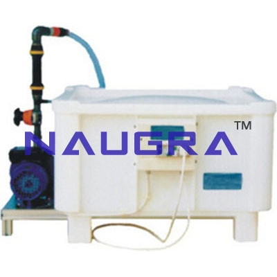
Technical Description Using the supplied weir plates, the measurement of flow rate in open channels can be investigated. They are used together ....
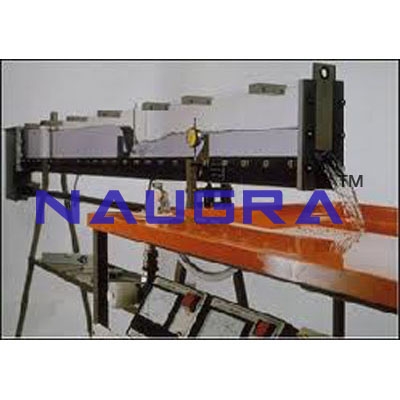
Technical Description The unit is used to demonstrate flow over weirs and the streamlines around different drag models....
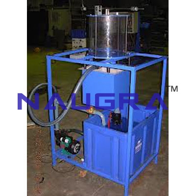
Technical Description The unit comprises a plexiglas tank in which a water jet discharged from a nozzle hits a surface and is deflected....
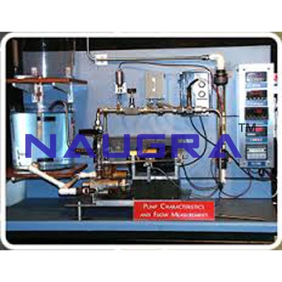
Technical Description The pump is a self-priming design. Experiments can be performed with the pump on its own, or in series with the pump on the bench....
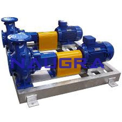
Technical Description The system comprises 2 identical centrifugal pumps that are connected together via pipes....
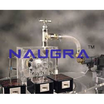
Technical Description A characteristic of impulse turbines is the complete conversion of pressure into kinetic energy at the exit of the supply nozzle....
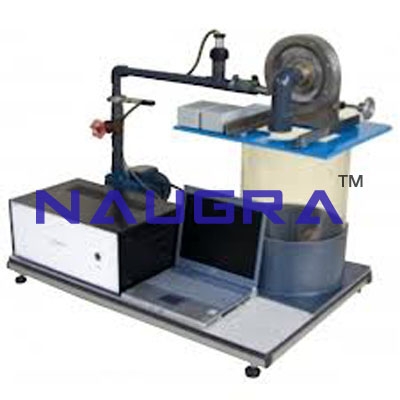
Technical Description A characteristic of reaction turbines is the conversion of pressure energy into kinetic energy at the guide vanes and rotor blades....
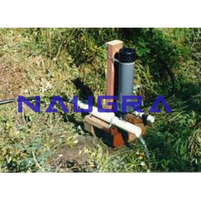
Technical Description Using this type of pump it is possible to pump water to a higher level without additional mechanical energy...
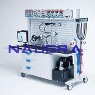
Technical Description The is part of a series of units that enable experiments to be performed on flow processes with the aid of a computer....
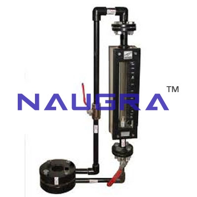
Technical Description Variable-area flow meters like the can be used for flow rate measurements in almost all media....
STRUCTURAL SPECIFICATIONS 1) Stainless structure. 2) Screws, nuts,...
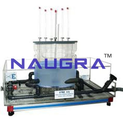
STRUCTURAL SPECIFICATIONS: 1) Stainless structure. 2) Screws, nuts, plates and all the metallic elements in stainless steel....
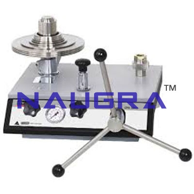
STRUCTURAL SPECIFICATIONS: 1) Stainless structure. 2) Screws, nuts, plates and all the metallic elements in stainless steel....
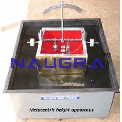
STRUCTURAL SPECIFICATIONS: 1) Stainless structure. 2) Screws, nuts, plates and all the metallic elements in stainless steel....
STRUCTURAL SPECIFICATIONS: 1) Stainless structure. 2) Screws, nuts, plates and all the metallic elements in stainless steel....
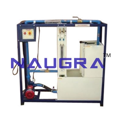
STRUCTURAL SPECIFICATIONS: 1) Stainless structure. 2) Screws, nuts, plates and all the metallic elements in stainless steel....
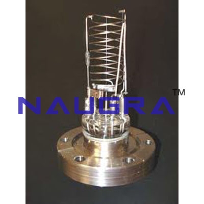
STRUCTURAL SPECIFICATIONS: 1) Stainless structure. 2) Screws, nuts, plates and all the metallic elements in stainless steel....
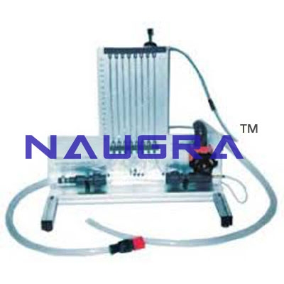
Unit for the study of Porous Beds in Venturi Tubes (Darcy's Equation) STRUCTURAL SPECIFICATIONS: 1) Stainless structure. 2) Screws, nuts, plates and all the metallic elements in stainless steel....
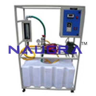
STRUCTURAL SPECIFICATIONS: 1) Stainless structure. 2) Screws, nuts, plates and all the metallic elements in stainless steel....
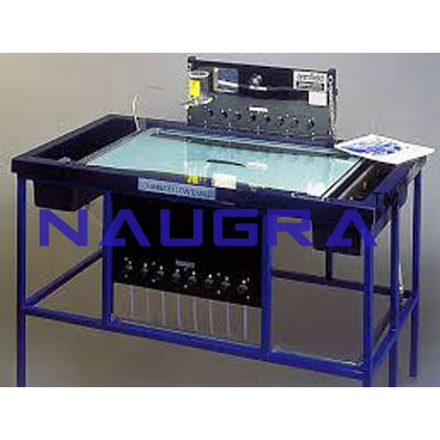
STRUCTURAL SPECIFICATIONS: 1) Stainless structure. 2) Screws, nuts, plates and all the metallic elements in stainless steel. 3) Diagram in the front panel with similar distribution to the elements in the real unit. 4) Quick connections for adaptation to feed hydraulics source. Fluid Mechanics Lab Equipments manufacturers...
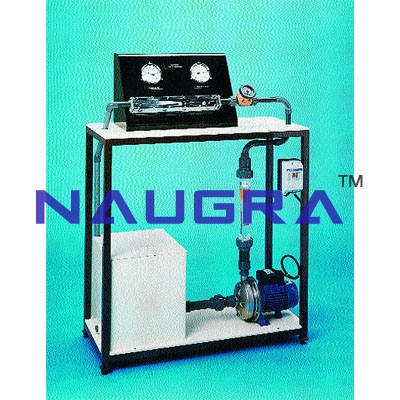
STRUCTURAL SPECIFICATIONS: 1) Stainless structure. 2) Screws, nuts, plates and all the metallic elements in stainless steel. 3) Diagram in the front panel with similar distribution to the elements in the real unit. 4) Quick connections for adaptation to feed hydraulics source. Fluid Mechanics Lab Equipments manufacturers...
STRUCTURAL SPECIFICATIONS: 1) Stainless structure. 2) Screws, nuts, plates and all the metallic elements in stainless steel. 3) Diagram in the front panel with similar distribution to the elements in the real unit. 4) Quick connections for adaptation to feed hydraulics source. Fluid Mechanics Lab Equipments manufacturers...
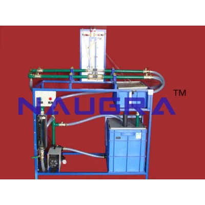
STRUCTURAL SPECIFICATIONS: 1) Stainless structure. 2) Screws, nuts, plates and all the metallic elements in stainless steel. 3) Diagram in the front panel with similar distribution to the elements in the real unit. 4) Quick connections for adaptation to feed hydraulics source. Fluid Mechanics Lab Equipments manufacturers...
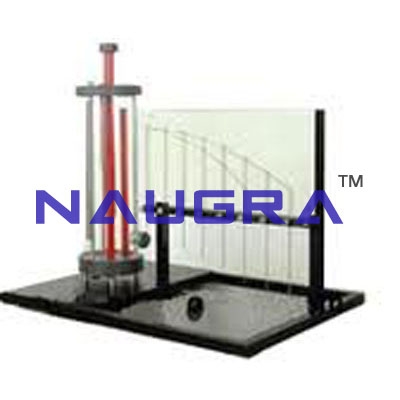
STRUCTURAL SPECIFICATIONS: 1) Stainless structure. 2) Screws, nuts, plates and all the metallic elements in stainless steel. 3) Diagram in the front panel with similar distribution to the elements in the real unit. 4) Quick connections for adaptation to feed hydraulics source Fluid Mechanics Lab Equipments manufacturers...
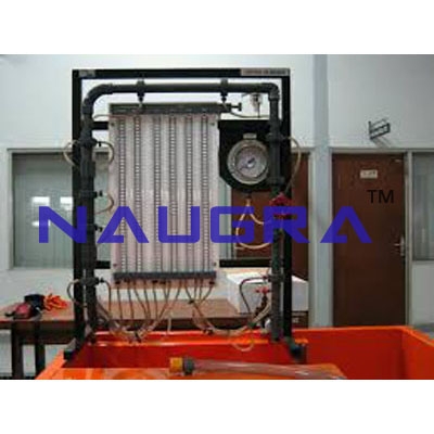
STRUCTURAL SPECIFICATIONS: 1) Stainless structure. 2) Screws, nuts, plates and all the metallic elements in stainless steel. 3) Diagram in the front panel with similar distribution to the elements in the real unit. 4) Quick connections for adaptation to feed hydraulics source. Fluid Mechanics Lab Equipments manufacturers...
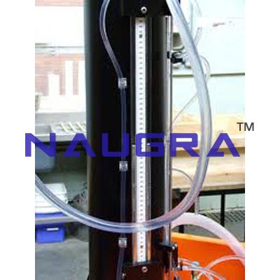
STRUCTURAL SPECIFICATIONS: 1) Stainless structure. 2) Screws, nuts, plates and all the metallic elements in stainless steel. 3) Diagram in the front panel with similar distribution to the elements in the real unit. 4) Quick connections for adaptation to feed hydraulics source Fluid Mechanics Lab Equipments manufacturers ...
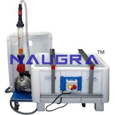
STRUCTURAL SPECIFICATIONS: 1) Stainless structure. 2) Screws, nuts, plates and all the metallic elements in stainless steel. 3) Diagram in the front panel with similar distribution to the elements in the real unit. 4) Quick connections for adaptation to feed hydraulics source. Fluid Mechanics Lab Equipments manufacturers...
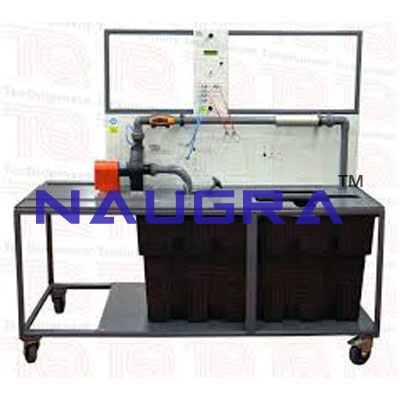
STRUCTURAL SPECIFICATIONS: 1) Stainless structure. 2) Screws, nuts, plates and all the metallic elements in stainless steel. 3) Diagram in the front panel with similar distribution to the elements in the real unit. 4) Quick connections for adaptation to feed hydraulics source. Fluid Mechanics Lab Equipments manufacturers...
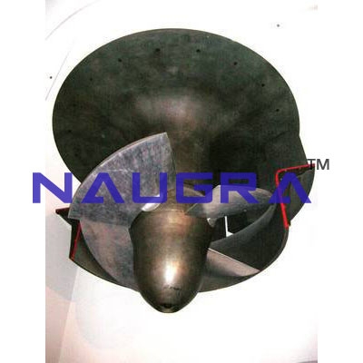
STRUCTURAL SPECIFICATIONS: 1) Stainless structure. 2) Screws, nuts, plates and all the metallic elements in stainless steel. 3) Diagram in the front panel with similar distribution to the elements in the real unit. 4) Quick connections for adaptation to feed hydraulics source. Fluid Mechanics Lab Equipments manufacturers...
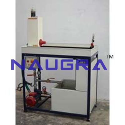
EXERCISES AND PRACTICAL POSSIBILITIES Some Practical Possibilities of the Unit: 1.- Load loss by friction in a rough pipe of 17 mm of interior diameter. 2.- Load loss by friction in a rough pipe of 23 mm of interior diameter. 3.- Load loss by friction in a smooth pipe of 6.5 mm of interior diameter. 4.- Load loss by friction in a smooth pipe of 16.5 mm of interior diameter. 5.- Load loss by friction in a smooth pipe of 26.5 mm of interior diameter. 6.- Influence of the diameter in the load loss by friction in rough pipes. 7.- Influence of the diameter in the load loss by friction in smooth pipes. 8.- Load loss by friction in smooth and rough pipes. 9.- Friction coefficient in a rough pipe of 17 mm of interior diameter. 10.-Friction coefficient in a rough pipe of 23 mm of interior diameter. 11.-Friction coefficient in a smooth pipe of 6.5 mm of interior diameter. 12.-Friction coefficient in a smooth pipe of 16.5 mm of interior diameter. 13.-Friction coefficient in a smooth pipe of 26.5 mm of interior diameter. 14.-Influence of the diameter in the friction coefficient in rough pipes. 15.-Influence of the diameter in the friction coefficient in smooth pipes. 16.-Friction coefficient in smooth and rough pipes. 17.-Load losses in the inclined seat valve. 18.-Load losses in the floodgate valve. 19.-Load losses in the filter. 20.-Load losses in the membrane valve. 21.-Load losses in an abrupt broadening. 22.-Load losses in the venturimeter 23.-Load losses in the diaphragm. 24.-Load losses in an abrupt contraction. 25.-Load losses in the accessories. 26.-Flow measurements by load loss in a venturimeter. 27.-Flow measurements by load loss in a diaphragm. 28.-Flow measurements by means of load loss. 29.-Load losses in a symmetrical bifurcation. 30.-Load losses after two 90º elbows. 31.-Load losses in a T-junction. 32.-Load losses for a 90º elbows. 33.-Load losses on the ball valve. 34.-Load losses for an elbow of 45º. 35.-Load losses in a inclined T-junction. 36.-Study of laminar regime. 37.-Study of turbulent regime. Other possible practices: 38.-Sensors calibration. Practices to be done by PLC Module (PLC-PI)+PLC Control Software: 39.-Control of the AFTC unit process through the control interface box without the computer. 40.-Visualization of all the sensors values used in the AFTC unit process. 41.-Calibration of all sensors included in the AFTC unit process. 42.-Hand on of all the actuators involved in the AFTC unit process. 43.-Realization of different experiments, in automatic way, without having in front the unit. (This experiment can be decided previously). 44.-Simulation of outside actions, in the cases do not exist hardware elements. (Example: test of complementary tanks, complementary industrial environment to the process to be studied, etc). 45.-PLC hardware general use and manipulation. 46.-PLC process application for AFTC unit. 47.-PLC structure. 48.-PLC inputs and outputs configuration. 49.-PLC configuration possibilities. 50.-PLC program languages. 51.-PLC different programming standard languages (literal structured, graphic, etc.). 52.-New configuration and development of new process. 53.-Hand on an established process. 54.-To visualize and see the results and to make comparisons with the AFTC unit process. 55.-Possibility of creating new process in relation with the AFTC unit. 56.-PLC Programming Exercises. 57.-Own PLC applications in accordance with teacher and student requirements. Fluid Mechanics Lab Equipments manufacturers...
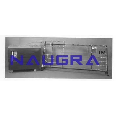
EXERCISES AND PRACTICAL POSSIBILITIES Some Practical Possibilities of the Unit: 1.- Load loss by friction in a rough pipe of 17 mm of interior diameter. 2.- Load loss by friction in a rough pipe of 23 mm of interior diameter. 3.- Load loss by friction in a smooth pipe of 6.5 mm of interior diameter. 4.- Load loss by friction in a smooth pipe of 16.5 mm of interior diameter. 5.- Load loss by friction in a smooth pipe of 26.5 mm of interior diameter. 6.- Influence of the diameter in the load loss by friction in rough pipes. 7.- Influence of the diameter in the load loss by friction in smooth pipes. 8.- Load loss by friction in smooth and rough pipes. 9.- Friction coefficient in a rough pipe of 17 mm of interior diameter. 10.- Friction coefficient in a rough pipe of 23 mm of interior diameter. 11.- Friction coefficient in a smooth pipe of 6.5 mm of interior diameter. 12.- Friction coefficient in a smooth pipe of 16.5 mm of interior diameter. 13.- Friction coefficient in a smooth pipe of 26.5 mm of interior diameter. 14.- Influence of the diameter in the friction coefficient in rough pipes. 15.- Influence of the diameter in the friction coefficient in smooth pipes. 16.- Friction coefficient in smooth and rough pipes. 17.- Load losses in the inclined seat valve. 18.- Load losses in the floodgate valve. 19.- Load losses in the filter. 20.- Load losses in the membrane valve. 21.- Load losses in an abrupt broadening. 22.- Load losses in the Venturi. 23.- Load losses in the diaphragm. 24.- Load losses in an abrupt contraction. 25.- Load losses in the accessories. 26.- Flow measurements by load loss in a Venturi. 27.- Flow measurements by load loss in a diaphragm. 28.- Flow measurements by means of load loss. 29.- Load losses in a symmetrical bifurcation. 30.- Load losses after two 90º elbows. 31.- Load losses in a T-junction. 32.- Load losses for a 90º elbows. 33.- Load losses on the ball valve. 34.- Load losses for an elbow of 45º. 35.- Load losses in a inclined T-junction. 36.- Study of laminar regime. 37.- Study of turbulent regime. Other possible practices: 38.- Filling of the manometers. 39.- Universal graph for the pipe calculation. Fluid Mechanics Lab Equipments manufacturers...
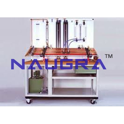
EXERCISES AND PRACTICAL POSSIBILITIES Some Practical Possibilities of the Unit: 1.- Load loss by friction in a rough pipe of 17 mm of interior diameter. 2.- Load loss by friction in a rough pipe of 23 mm of interior diameter. 3.- Load loss by friction in a smooth pipe of 6.5 mm of interior diameter 4.- Load loss by friction in a smooth pipe of 16.5 mm of interior diameter. 5.- Load loss by friction in a smooth pipe of 26.5 mm of interior diameter. 6.- Influence of the diameter in the load loss by friction in rough pipes. 7.- Influence of the diameter in the load loss by friction in smooth pipes. 8.- Load loss by friction in smooth and rough pipes. 9.- Friction coefficient in a rough pipe of 17 mm of interior diameter. 10.- Friction coefficient in a rough pipe of 23 mm of interior diameter. 11.- Friction coefficient in a smooth pipe of 6.5 mm of interior diameter. 12.- Friction coefficient in a smooth pipe of 16.5 mm of interior diameter. 13.- Friction coefficient in a smooth pipe of 26.5 mm of interior diameter. 14.- Influence of the diameter in the friction coefficient in rough pipes. 15.- Influence of the diameter in the friction coefficient in smooth pipes. 16.- Friction coefficient in smooth and rough pipes. 17.- Load losses in the inclined seat valve. 18.- Load losses in the floodgate valve. 19.- Load losses in the filter. 20.- Load losses in the membrane valve. 21.- Load losses in an abrupt broadening. 22.- Load losses in the Venturi. 23.- Load losses in the diaphragm. 24.- Load losses in an abrupt contraction. 25.- Load losses in the accessories. 26.- Flow measurements by load loss in a Venturi. 27.- Flow measurements by load loss in a diaphragm. 28.- Flow measurements by means of load loss. 29.- Load losses in a symmetrical bifurcation. 30.- Load losses after two 90º elbows. 31.- Load losses in a T-junction. 32.- Load losses for a 90º elbows. 33.- Load losses on the ball valve. 34.- Load losses for an elbow of 45º. 35.- Load losses in a inclined T-junction. 36.- Study of laminar regime. 37.- Study of turbulent regime. Other possible practices: 38.- Filling of the manometers. 39.- Universal graph for the pipe calculation. Fluid Mechanics Lab Equipments manufacturers...
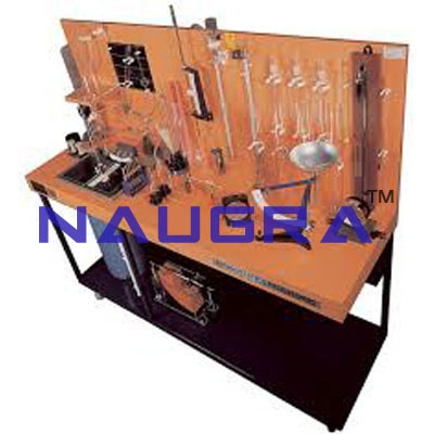
EXERCISES AND PRACTICAL POSSIBILITIES Some Practical Possibilities of the Unit: 1.- Load loss by friction in a rough pipe of 17 mm of interior diameter. 2.- Load loss by friction in a rough pipe of 23 mm of interior diameter. 3.- Load loss by friction in a smooth pipe of 6.5 mm of interior diameter. 4.- Load loss by friction in a smooth pipe of 16.5 mm of interior diameter. 5.- Load loss by friction in a smooth pipe of 26.5 mm of interior diameter. 6.- Influence of the diameter in the load loss by friction in rough pipes. 7.- Influence of the diameter in the load loss by friction in smooth pipes. 8.- Load loss by friction in smooth and rough pipes. 9.- Friction coefficient in a rough pipe of 17 mm of interior diameter. 10.- Friction coefficient in a rough pipe of 23 mm of interior diameter. 11.- Friction coefficient in a smooth pipe of 6.5 mm of interior diameter. 12.- Friction coefficient in a smooth pipe of 16.5 mm of interior diameter. 13.- Friction coefficient in a smooth pipe of 26.5 mm of interior diameter. 14.- Influence of the diameter in the friction coefficient in rough pipes. 15.- Influence of the diameter in the friction coefficient in smooth pipes. 16.- Friction coefficient in smooth and rough pipes. 17.- Load losses in the inclined seat valve. 18.- Load losses in the floodgate valve. 19.- Load losses in the filter. 20.- Load losses in the membrane valve. 21.- Load losses in an abrupt broadening. 22.- Load losses in the Venturi. 23.- Load losses in the diaphragm. 24.- Load losses in an abrupt contraction. 25.- Load losses in the accessories. 26.- Flow measurements by load loss in a Venturi. 27.- Flow measurements by load loss in a diaphragm. 28.- Flow measurements by means of load loss. 29.- Load losses in a symmetrical bifurcation. 30.- Load losses after two 90º elbows. 31.- Load losses in a T-junction. 32.- Load losses for a 90º elbows. 33.- Load losses on the ball valve. 34.- Load losses for an elbow of 45º. 35.- Load losses in a inclined T-junction. 36.- Study of laminar regime. 37.- Study of turbulent regime. Other possible practices: 38.- Filling of the manometers. 39.- Universal graph for the pipe calculation. Fluid Mechanics Lab Equipments manufacturers...
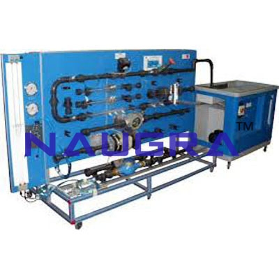
EXERCISES AND PRACTICAL POSSIBILITIES Some Practical Possibilities of the Unit: 1.- Density and specific gravity measurements. 2.- Viscosity measurement. 3.- Capillarity effect observation. 4.- Capillarity raising measurement. 5.- Free surface of a static liquid. 6.- Effect of a liquid on a free surface. 7.- Measurement of liquid levels. 8.- Pressure center in a smooth surface. 9.- Center of pressures for partial immersion. 10.-Center of pressures for total immersion. 11.- Calibration of a Bourdon manometer. 12.-Hysteresis curve determination. 13.-Use of a water manometer on mercury. 14.-Use of an air manometer on mercury. 15.-Use of a U-shaped manometer for determining the differential pressure. 16.-Archimedes principle. 17.-Determination of the metacentric height. 18.-Study of stability of a floating body. Angular displacements. 19.-Study of stability of a floating body. Different positions of the center of gravity. 20.-Operation and comparison of results obtained with different measuring instruments. Other possible practices: 21.-Table of the atmospheric pressure in function of the height. 22.-Use instructions of the scale of Archimedes. Fluid Mechanics Lab Equipments manufacturers...
EXERCISES AND PRACTICAL POSSIBILITIES Some Practical Possibilities of the Unit: Ideal flow around submerged bodies: 1.- Ideal flow around a cylinder. 2.- Ideal flow around a surface. 3.- Ideal flow around a body in pick. Ideal flow in channels and edges: 4.- Ideal flow in a convergent channel. 5.- Ideal flow in a divergent channel. 6.- Ideal flow through a curve of 90ª. 7.- Ideal flow through a sudden contraction. 8.- Ideal flow through a sudden broadening. 9.- Substitution of a current line for a solid border. Ideal flow associated to drains and sources: 10.- Formation of a half-body of Rankine. 11.- Formation of a Rankine oval. 12.- Superposition of drains and sources. Fluid Mechanics Lab Equipments manufacturers...
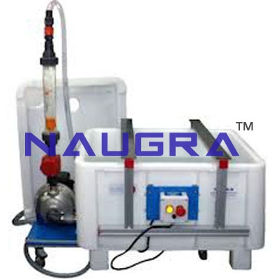
EXERCISES AND PRACTICAL POSSIBILITIES Some Practical Possibilities of the Unit: 1.- Load loss by friction in a rough pipe of 17 mm of interior diameter. 2.- Load loss by friction in a rough pipe of 23 mm of interior diameter. 3.- Load loss by friction in a smooth pipe of 6.5 mm of interior diameter. 4.- Load loss by friction in a smooth pipe of 16.5 mm of interior diameter. 5.- Load loss by friction in a smooth pipe of 26.5 mm of interior diameter. 6.- Influence of the diameter in the load loss by friction in rough pipes. 7.- Influence of the diameter in the load loss by friction in smooth pipes. 8.- Load loss by friction in smooth and rough pipes. 9.- Friction coefficient in a rough pipe of 17 mm of interior diameter. 10.-Friction coefficient in a rough pipe of 23 mm of interior diameter. 11.-Friction coefficient in a smooth pipe of 6.5 mm of interior diameter. 12.-Friction coefficient in a smooth pipe of 16.5 mm of interior diameter. 13.-Friction coefficient in a smooth pipe of 26.5 mm of interior diameter. 14.-Influence of the diameter in the friction coefficient in rough pipes. 15.-Influence of the diameter in the friction coefficient in smooth pipes. 16.-Friction coefficient in smooth and rough pipes. 17.-Load losses in the inclined seat valve. 18.-Load losses in the floodgate valve. 19.-Load losses in the filter. 20.-Load losses in the membrane valve. 21.-Load losses in an abrupt broadening. 22.-Load losses in the venturimeter 23.-Load losses in the diaphragm. 24.-Load losses in an abrupt contraction. 25.-Load losses in the accessories. 26.-Flow measurements by load loss in a venturimeter. 27.-Flow measurements by load loss in a diaphragm. 28.-Flow measurements by means of load loss. 29.-Load losses in a symmetrical bifurcation. 30.-Load losses after two 90º elbows. 31.-Load losses in a T-junction. 32.-Load losses for a 90º elbows. 33.-Load losses on the ball valve. 34.-Load losses for an elbow of 45º. 35.-Load losses in a inclined T-junction. 36.-Study of laminar regime. 37.-Study of turbulent regime. Other possible practices: 38.-Sensors calibration. Practices to be done by PLC Module (PLC-PI)+PLC Control Software: 39.-Control of the AFTC unit process through the control interface box without the computer. 40.-Visualization of all the sensors values used in the AFTC unit process. 41.-Calibration of all sensors included in the AFTC unit process. 42.-Hand on of all the actuators involved in the AFTC unit process. 43.-Realization of different experiments, in automatic way, without having in front the unit. (This experiment can be decided previously). 44.-Simulation of outside actions, in the cases donot exist hardware elements. (Example: test of complementary tanks, complementary industrial environment to the process to be studied, etc). 45.-PLC hardware general use and manipulation. 46.-PLC process application for AFTC unit. 47.-PLC structure. 48.-PLC inputs and outputs configuration. 49.-PLC configuration possibilities. 50.-PLC program languages. 51.-PLC different programming standard languages (literal structured, graphic, etc.). 52.-New configuration and development of new process. 53.-Hand on an established process. 54.-To visualize and see the results and to make comparisons with the AFTC unit process. 55.-Possibility of creating new process in relation with the AFTC unit. 56.-PLC Programming Exercises. 57.-Own PLC applications in accordance with teacher and student requirements. Fluid Mechanics Lab Equipments manufacturers...
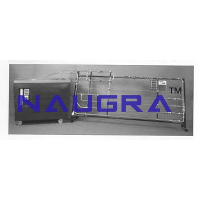
EXERCISES AND PRACTICAL POSSIBILITIES Some Practical Possibilities of the Unit: 1.- Load loss by friction in a rough pipe of 17 mm of interior diameter. 2.- Load loss by friction in a rough pipe of 23 mm of interior diameter. 3.- Load loss by friction in a smooth pipe of 6.5 mm of interior diameter. 4.- Load loss by friction in a smooth pipe of 16.5 mm of interior diameter. 5.- Load loss by friction in a smooth pipe of 26.5 mm of interior diameter. 6.- Influence of the diameter in the load loss by friction in rough pipes. 7.- Influence of the diameter in the load loss by friction in smooth pipes. 8.- Load loss by friction in smooth and rough pipes. 9.- Friction coefficient in a rough pipe of 17 mm of interior diameter. 10.- Friction coefficient in a rough pipe of 23 mm of interior diameter. 11.- Friction coefficient in a smooth pipe of 6.5 mm of interior diameter. 12.- Friction coefficient in a smooth pipe of 16.5 mm of interior diameter. 13.- Friction coefficient in a smooth pipe of 26.5 mm of interior diameter. 14.-Influence of the diameter in the friction coefficient in rough pipes. 15.- Influence of the diameter in the friction coefficient in smooth pipes. 16.- Friction coefficient in smooth and rough pipes. 17.- Load losses in the inclined seat valve. 18.- Load losses in the floodgate valve. 19.- Load losses in the filter. 20.- Load losses in the membrane valve. 21.- Load losses in an abrupt broadening. 22.- Load losses in the Venturi. 23.- Load losses in the diaphragm. 24.- Load losses in an abrupt contraction. 25.- Load losses in the accessories. 26.- Flow measurements by load loss in a Venturi. 27.- Flow measurements by load loss in a diaphragm. 28.- Flow measurements by means of load loss. 29.- Load losses in a symmetrical bifurcation. 30.- Load losses after two 90º elbows. 31.- Load losses in a T-junction. 32.- Load losses for a 90º elbows. 33.- Load losses on the ball valve. 34.- Load losses for an elbow of 45º. 35.- Load losses in a inclined T-junction. 36.- Study of laminar regime. 37.- Study of turbulent regime. Other possible practices: 38.- Filling of the manometers. 39.- Universal graph for the pipe calculation. Fluid Mechanics Lab Equipments manufacturers...
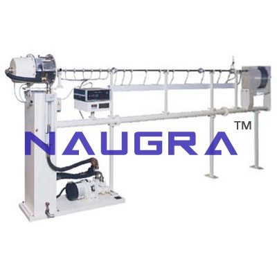
EXERCISES AND PRACTICAL POSSIBILITIES Some Practical Possibilities of the Unit: 1.- Load loss by friction in a rough pipe of 17 mm of interior diameter. 2.- Load loss by friction in a rough pipe of 23 mm of interior diameter. 3.- Load loss by friction in a smooth pipe of 6.5 mm of interior diameter 4.- Load loss by friction in a smooth pipe of 16.5 mm of interior diameter. 5.- Load loss by friction in a smooth pipe of 26.5 mm of interior diameter. 6.- Influence of the diameter in the load loss by friction in rough pipes. 7.- Influence of the diameter in the load loss by friction in smooth pipes. 8.- Load loss by friction in smooth and rough pipes. 9.- Friction coefficient in a rough pipe of 17 mm of interior diameter. 10.- Friction coefficient in a rough pipe of 23 mm of interior diameter. 11.- Friction coefficient in a smooth pipe of 6.5 mm of interior diameter. 12.- Friction coefficient in a smooth pipe of 16.5 mm of interior diameter. 13.- Friction coefficient in a smooth pipe of 26.5 mm of interior diameter. 14.- Influence of the diameter in the friction coefficient in rough pipes. 15.- Influence of the diameter in the friction coefficient in smooth pipes. 16.- Friction coefficient in smooth and rough pipes. 17.- Load losses in the inclined seat valve. 18.- Load losses in the floodgate valve. 19.- Load losses in the filter. 20.- Load losses in the membrane valve. 21.- Load losses in an abrupt broadening. 22.- Load losses in the Venturi. 23.- Load losses in the diaphragm. 24.- Load losses in an abrupt contraction. 25.- Load losses in the accessories. 26.- Flow measurements by load loss in a Venturi. 27.- Flow measurements by load loss in a diaphragm. 28.- Flow measurements by means of load loss. 29.- Load losses in a symmetrical bifurcation. 30.- Load losses after two 90º elbows. 31.- Load losses in a T-junction. 32.- Load losses for a 90º elbows. 33.- Load losses on the ball valve. 34.- Load losses for an elbow of 45º. 35.- Load losses in a inclined T-junction. 36.- Study of laminar regime. 37.- Study of turbulent regime. Other possible practices: 38.- Filling of the manometers. 39.- Universal graph for the pipe calculation. Fluid Mechanics Lab Equipments manufacturers...
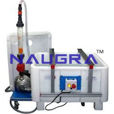
EXERCISES AND PRACTICAL POSSIBILITIES Some Practical Possibilities of the Unit: 1.- Head losses in a PVC pipe. 2.- Head losses in an aluminium pipe. 3.- Head losses in a methacrylate pipe. 4.- Study of head losses in pipes of the same material. 5.- Study of head losses in function of the material. 6.- Friction coefficient in a PVC pipe. 7.- Friction coefficient in an aluminium pipe. 8.- Friction coefficient in a methacrylate pipe. 9.- Study of the friction coefficient in function of the material. 10.- Study of the friction coefficient in function of the diameter. 11.- Parallel network configuration for pipes of same material and different diameter. 12.- Parallel network configuration for pipes of different material and same diameter. 13.- Series network configuration for pipes of different material and different diameter. 14.- Series network configuration for pipes of different material and same diameter. 15.- Characteristics of a circular circuit. 16.- Double piping circuit. Other possible practices: 17.- Sensors calibration. Practices to be done by PLC Module (PLC-PI)+PLC Control Software: 18.- Control of the AMTC unit process through the control interface box without the computer. 19.- Visualization of all the sensors values used in the AMTC unit process. 20.- Calibration of all sensors included in the AMTC unit process. 21.- Hand on of all the actuators involved in the AMTC unit process. 22.- Realization of different experiments, in automatic way, without having in front the unit. (This experiment can be decided previously). 23.- Simulation of outside actions, in the cases do not exist hardware elements. (Example: test of complementary tanks, complementary industrial environment to the process to be studied, etc). 24.- PLC hardware general use and manipulation. 25.- PLC process application for AMTC unit. 26.- PLC structure. 27.- PLC inputs and outputs configuration. 28.- PLC configuration possibilities. 29.- PLC program languages. 30.- PLC different programming standard languages. 31.- New configuration and development of new process. 32.- Hand on an established process. 33.- To visualize and see the results and to make comparisons with the AMTC unit process. 34.- Possibility of creating new process in relation with the AMTC unit. 35.- PLC Programming Exercises. 36.- Own PLC applications in accordance with teacher and student requirements. Fluid Mechanics Lab Equipments manufacturers...
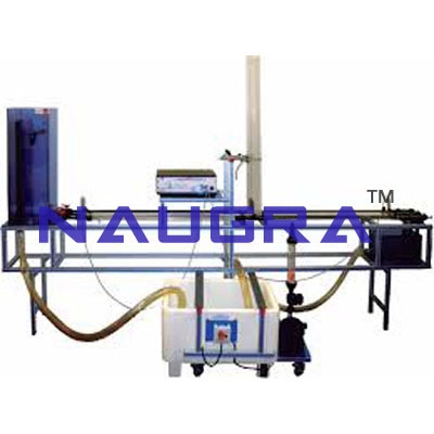
Exercises and Practical Possibilities to be done with Main Items 1.- Characterization of the water hammer phenomenon in pipes. 2.- Subduing the water hammer effects. 3.- Calculation of energy losses in pipes. 4.- Influences of the pipe diameter on the speed propagation. 5.- Subduing of the effects of the water hammer through abrupt expansions. Additional practical possibilities: 6.- Sensors calibration. Other possibilities to be done with this Unit: 7.- Many students view results simultaneously. To view all results in real time in the classroom by means of a projector or an electronic blackboard. 8.- Open Control, Multicontrol and Real Time Control. This unit allows intrinsically and/or extrinsically to change the span, gain; proportional, integral, derivate parameters; etc in real time. 9.- The Computer Control System with SCADA allows a real industrial simulation. 10.- This unit is totally safe as uses mechanical, electrical and electronic, and software safety devices. 11.- This unit can be used for doing applied research. 12.- This unit can be used for giving training courses to Industries even to other Technical Education Institutions. 13.- Control of the EGAC unit process through the control interface box without the computer. 14.- Visualization of all the sensors values used in the EGAC unit process. - By using PLC-PI additional 19 more exercises can be done. - Several other exercises can be done and designed by the user. Fluid Mechanics Lab Equipments manufacturers...
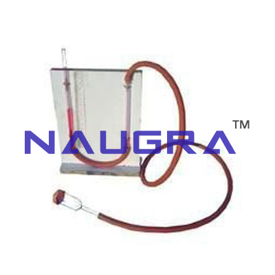
Specifications :- This multimanometer has been designed for operating with Pitot’ s tube. It allows finding the pressure between two points or two fluids. Anodized aluminium structure and panel in painted steel (epoxi paint). 2 U-shape Glass Manometers of 500 mm. length. Millimeter precision rules of 500 mm. length. 3 points for pressure measurement. Manuals: This unit is supplied with the following manuals: Required Services, Assembly and Installation, Starting-up, Safety, Maintenance & Practices Manuals. *Dimensions: 250 x 500 x 870 mm. approx. Weight: 3 Kg. approx. Fluid Mechanics Lab Equipments manufacturers...
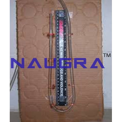
Designed for wall assembly. Anodized aluminium structure and panel in painted steel (epoxi paint). U-shape manometer of 1000 mm. length. Millimeter precision rules of 1000 mm. length. Upper collector. Lower collector. Drain valve. Manuals: This unit is supplied with the following manuals: Required Services, Assembly and Installation, Starting-up, Safety, Maintenance & Practices Manuals. Dimensions: 170 x 40 x 1400 mm. approx. Weight: 2 Kg. approx. Fluid Mechanics Lab Equipments manufacturers...
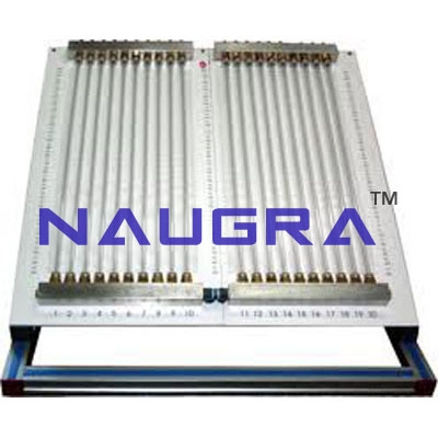
Anodized aluminium structure. Approx. 30º inclination. 20 manometric tubes of 250 mm. length. Tubes inner diameter: 8 mm., to avoid bubbles. Water tank for filling. 20 points for differential pressure measurement, with key. Common collector. Drain valve. Millimeter precision rules of 250 mm. length. Manuals: This unit is supplied with the following manuals: Required Services, Assembly and Installation, Starting-up, Safety, Maintenance & Practices Manuals. Dimensions: 1400 x 1400 x 700 mm. approx. Weight: 10 Kg. approx....

Anodized aluminium structure and panel in painted steel (epoxi paint). Vertical position. 8 Manometric tubes of 500 mm. length. Tubes inner diameter: 8 mm., to avoid bubbles. Air pump for pressurization. 8 points for differential pressure measurement, with key. Common collector. Non-return valve. Drain valve. Millimeter precision rules of 500 mm. length. Manuals: This unit is supplied with the following manuals: Required Services, Assembly and Installation, Starting-up, Safety, Maintenance & Practices Manuals. Dimensions: 300 x 500 x 870 mm. approx. Weight: 4 Kg. approx. Fluid Mechanics Lab Equipments manufacturers...
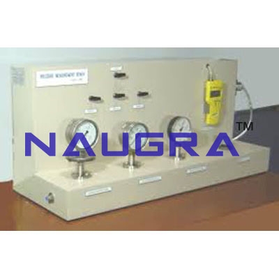
Bench-top unit. Anodized aluminium structure and panel in painted steel (epoxi paint). Diagram in the front panel. Vacuum-meter of range (-9800 [mm H2O] to 0). Vacuum-meter of range (-1000 [mm H2O] to 0). Manometer of range (0 to 1000 [mm H2O] ). Manometer of range (0 to 2.5 [bars]). Mobile Piston (syringe). 8 valves. Non-return valve. Polyurethane tubes. This system is supplied with atm, bares, psi, mmHg, mm H2O, conversion tables. This system allows the calibration of 6 sensors (same type) simultaneously. Manuals: This unit is supplied with the following manuals: Required Services, Assembly and Installation, Starting-up, Safety, Maintenance & Practices Manuals. Dimensions: 720 x 300 x 570 mm. approx. Weight: 15 Kg. approx. Fluid Mechanics Lab Equipments manufacturers...
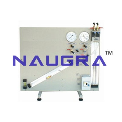
EXERCISES AND PRACTICAL POSSIBILITIES Some Practical Possibilities of the Unit: 1.- Familiarisation with different pressure measurement methods. 2.- Function and characteristics of a Bourdon type gauge. 3.- Function and characteristics of a “U” tube manometers. 4.- Pressure measurements with U-tube manometers. 5.- Pressure measurements with Bourdon type manometers. 6.- Comparison of different types of pressure measurement. 7.- Comparison of different pressure measurement methods. 8.- Calibration of a pressure gauge. 9.- Determination of gauge errors. Fluid Mechanics Lab Equipments manufacturers...
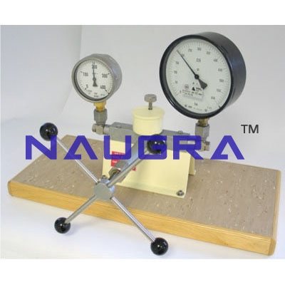
Specification The unit is a seft-contained and portable dead weight precision pressure gauge calibrator. This unit allows pressure gauges to be accurately calibrated within the range 1-300 bar. Calibrates gauges 1-300 bar range to ±0.015% of reading. Two pistons allow calibration over a wide range of pressures. Oil is used as the hydraulic fluid. Minimum standard weight increment is 0.05 bar. A set of weights, adaptors and spare seals are supplied. Laboratory calibration certificate. Carrying case. Dimensions: 500 x 350 x 400 mm. approx. Weight: 35 Kg. approx. Fluid Mechanics Lab Equipments manufacturers...
EXERCISES AND PRACTICAL POSSIBILITIES Some Practical Possibilities of the Unit: 1.- Study the concept of pressure. 2.- Study of the concepts of measurement and calibration (gauge and absolute pressures, zero error, non-linearity, scale error, conversion of arbitrary scale into energy units). 3.- Study of pressure scales. 4.- Study of the function of a dead-weight pressure calibrator. 5.- Study of the operation of a Bourdon type manometer. 6.- Study of the characteristic behaviour of a Bourdon type manometer. 7.- Calibration of a Bourdon type manometer in engineering units. 8.- Calibration of a Bourdon type manometer in arbitrary units (angular displacement of needle). 9.- Study of the characteristic behaviour of a pressure sensor. 10.- Calibration of a pressure sensor and signal conditioning circuit in engineering units. 11.- Calibration of a pressure sensor (voltage output from sensor). 12.- Study of the sources of error in measurement and calibration (signal conditioning, display resolution; wear, friction and backlash, etc.). 13.- Study of calibration of conditioning circuits and display using a reference signal. Fluid Mechanics Lab Equipments manufacturers...
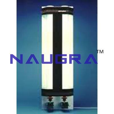
Unit mounted on an anodized aluminium structure with panels in painted steel.Two transparent measuring cylinders:Internal diameter: 114 mm.External diameter: 120 mm.Length: 1.3 m.Both cylinders are marked longitudinally every 50 cm, so that the distance the ball travels after being thrown inside can be read. Two light sources placed between the tubes for ease of viewing. Power: 58 W.Two guides to aid the introduction of particles at the top of the tubes with the minimum disturbance to the liquid.Six couplings for the guides to make the introduction of smaller balls possible (5 mm, 10 mm and 15 mm).Two ball valves and two gate valves to aid the removal of balls from the bottom of the tubes, without a large loss of liquid.Sets of balls of different sizes:Ball 1 is made of stainless steel, diameter = 5mm.Ball 2 is made of stainless steel, diameter = 10mm.Ball 3 is made of stainless steel, diameter = 15mm.Ball 4 is made of stainless steel, diameter = 20mm.Ball 5 is made of stainless steel, diameter = 25mm.A stopwatch.Two plastic beakers with a capacity of 0.50 l. each one.Cables and accessories, for normal operation.Manuals: This unit is supplied with the following manuals: Required Services, Assembly and Installation, Starting-up, Safety, Maintenance & Practices Manuals. Fluid Mechanics Lab Equipments manufacturers...
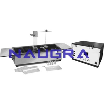
EXERCISES AND PRACTICAL POSSIBILITIES Some Practical Possibilities of the Unit: 1.- Visualising two-dimensional flow using hydrogen bubbles. 2.- Analogy of aerodynamic flow. 3.- Understanding laminar and turbulent flow. 4.- Visualization of boundary layer. 5.- Demonstration of the boundary layer growth. 6.- Quantitative observing of flow measuring devices. 7.- Demonstration of boundary layer separation and eddy formation. 8.- Quantitative analysis of flow patterns using pulsed bubbles. 9.- Observation of flow around standard shapes (cylinder, aerofoil, etc.). 10.- Observation of flow around user created models. Fluid Mechanics Lab Equipments manufacturers...
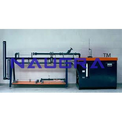
EXERCISES AND PRACTICAL POSSIBILITIES Some Practical Possibilities of the Unit: 1.- To demonstrate the important characteristics of fourteen types of flow meters used in the measurement of water flow through pipes or open channels. 2.- Comparing the use, application and limitations of different types of flowmeters. 3.- To study the application of Bernoulli’s Theorem. 4.-Understanding the principles on which various types of flow meters are based. 5.-Implications of performance, convenience, accuracy, head loss, etc. on flow meters selection. 6.-Effect of the air in the hydraulic stream on flow meter performance. 7.- To use manometers to measure pressure drop. 8.- Relating pressure drop across a flow meter to flow rate. 9.-Measure error determination using the venturimeter. 10.- Factor Cd determination in the venturi. 11.- Strangulation determination in the venturi. 12.-Measure error determination using the orifice plate. 13.- Factor Cd determination in the orifice plate. 14.- Effective area determination in the orifice plate. 15.-Measure error determination using the Pitot tube. 16.- Factor Cd determination in the Pitot tube. 17.- Measure error using the swinging flap meter. 18.- Measure error using the rotary piston meter. 19.- Measure error using the shunt gapmeter. 20.- Energy loss comparison in the different meters. 21.-Measure error using the helical rotary type flowmeter. 22.- Measure error using the inferential multistream type flowmeter. 23.- Broad crested weir. 24.- Crump weir. 25.- “H” flume. 26.- Washington flume. Fluid Mechanics Lab Equipments manufacturers...
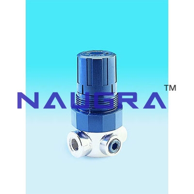
Exercise & Practical Posibilities 1. To use pressure regulator for high buildings.2. Determination of air pressure tank and pump.3. Study and investigation of air pressure tank supported water system. 4. Adjustment of pressure switch Fluid Mechanics Lab Equipments manufacturers...
EXERCISES AND PRACTICAL POSSIBILITIES Some Practical Possibilities of the Unit: 1.- Determination of the superficial dragging. 2.- Hydrograph curve, strong storm. 3.- Calculation of concentration time for a shortstorm. 4.- Storm hydrographs from single or multiple storms. 5.- Storm hydrograph from a previously saturated catchment. 6.- Storm runoff from an impermeable catchment. 7.- Drainage density determination. 8.- Effect of a moving storm flood hydrograph. 9.- Effect of a reservoir storage on flood hydrograph. 10.- Effect of land drains on flood hydrograph. 11.- Reservoir filling and flooding. 12.- Gravity force of water. 13.- Fluvial-mechanical experiments. 14.- Model stream flow in alluvial material. 15.- Sediment transport in river models. 16.- Formation and development of river features over time. 17.- Meandering river. 18.- Erosion on river beds and current speed. 19.- Sediment transport, bedload motion, scour and erosion. 20.- Underground water capture studies. 21.- Well depression cone. 22.- Interaction of depression cones by two adjoining wells. 23.- Well in the centre of a circular island. 24.- Draw-down curves for one well and two wells systems. Other possible practices: 25.- Sensors calibration. Practices to be done by PLC Module (PLC-PI)+PLC Control Software: 26.- Control of the ESHC unit process through the control interface box without the computer. 27.- Visualization of all the sensors values used in the ESHC unit process. 28.- Calibration of all sensors included in the ESHC unit process. 29.- Hand on of all the actuators involved in the ESHC unit process. Fluid Mechanics Lab Equipments manufacturers...
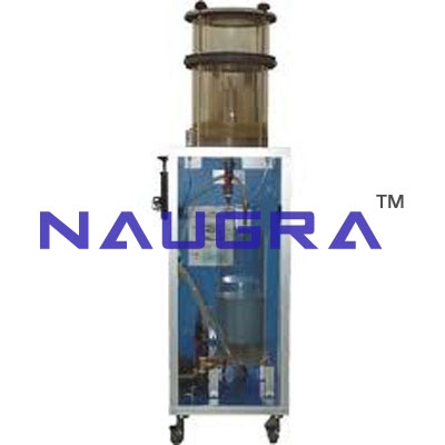
EXERCISES AND PRACTICAL POSSIBILITIES Some Practical Possibilities of the Unit: 1.- Determination of the superficial dragging. 2.- Hydrograph curve, strong storm. 3.- Calculation of concentration time for a short storm. 4.- Storm hydrographs from single or multiple storms. 5.- Storm hydrograph from a previously saturated catchment. 6.- Storm runoff from an impermeable catchment. 7.- Drainage density determination. 8.- Effect of a moving storm flood hydrograph. 9.- Effect of a reservoir storage on flood hydrograph. 10.- Effect of land drains on flood hydrograph. 11.- Reservoir filling and flooding. 12.- Gravity force of water. 13.- Fluvial-mechanical experiments. 14.- Model stream flow in alluvial material. 15.- Sediment transport in river models. 16.- Formation and development of river features over time. 17.- Meandering river. 18.- Erosion on river beds and current speed. 19.- Sediment transport, bedload motion, scour and erosion. 20.- Underground water capture studies. 21.- Well depression cone. 22.- Interaction of depression cones by two adjoining wells. 23.- Well in the centre of a circular island. 24.- Draw-down curves for one well and two wells systems. Fluid Mechanics Lab Equipments manufacturers...
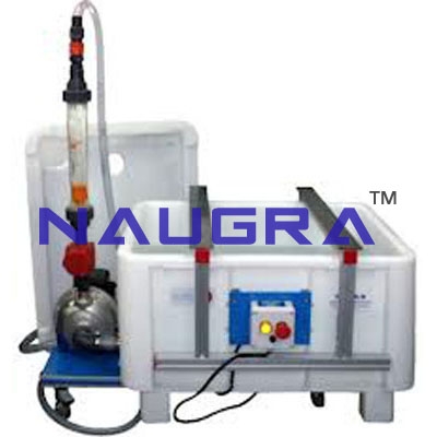
EXERCISES AND PRACTICAL POSSIBILITIES Some Practical Possibilities of the Unit: 1.- Determination of the superficial dragging. 2.- Hydrograph curve, strong storm. 3.- Calculation of concentration time for a short storm. 4.- Storm hydrographs from single or multiple storms. 5.- Storm hydrograph from a previously saturated catchment. 6.- Storm runoff from an impermeable catchment. 7.- Drainage density determination. 8.- Effect of a moving storm flood hydrograph. 9.- Effect of a reservoir storage on flood hydrograph. 10.- Effect of land drains on flood hydrograph. 11.- Reservoir filling and flooding. 12.- Gravity force of water. 13.- Fluvial-mechanical experiments. 14.- Model stream flow in alluvial material. 15.- Sediment transport in river models. 16.- Formation and development of river features over time. 17.- Meandering river. 18.- Erosion on river beds and current speed. 19.- Sediment transport, bedload motion, scour and erosion. 20.- Underground water capture studies. 21.- Well depression cone. 22.- Interaction of depression cones by two adjoining wells. 23.- Well in the centre of a circular island. 24.- Draw-down curves for one well and two wells systems. Other possible practices: 25.- How to fill the manometric tubes. 26.- How to use the Flowmeter (orifice plate). Fluid Mechanics Lab Equipments manufacturers...
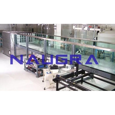
Computer Controlled Flow Channels (section: 80 x 300 mm).(several lengths) Exercises and Practical Possibilities to be done with Main Items 1.- Measurement of the water height and the velocity along the channel. 2.- Measurement of the flow with weirs of thin wall. 3.- Measurement of flow with changes in the channel section. 4.- Measurement of flow using Venturi flume. 5.- Control of the flow by gates. 6.- Level control using syphons. 7.- Flow on overflow dams. 8.- Flow among the pillars of a bridge. 9.- Connection of a channel to a culvert. 10.- Characterization of the hydraulic jump. 11.- Profiles of the water free surface. 12.- Investigation of flow and supercritical flow states. 13.- Measurement of water levels. 14.- Discharge processes on an underwater weir. 15.- Amount of energy in flows in open channels. 16.- Function of a syphon weir. 17.- Flow rate and drain coefficients of a syphon weir. 18.- Pipe flows. 19.- Comparison of overflow and syphon weirs. 20.- Observation of the throw of the water. 21.- Generation of different flow states by damming the down-stream water. 22.- Observation of the flow under an undershot weir: -Observation of hydraulic motion on discharge. 23.- Relationship between dam height and discharge. 24.- Observation of discharges under a radial gate: -Observation of hydraulic motion on discharge. 25.- Hydrostatic pressure on a weir. 26.- Investigations on waves. 27.- Behaviour of structures in rough sea. 28.- Applying and understanding Manning’s formula. 29.- Understanding sub- and super-critical flow. 30 Learning how to apply force-momentum and steady flow energy equations to simple flow situations. 31.- Investigation of the transition from running to shooting flow. Additional practical possibilities: 32.- Sensors calibration. 33.- Filling of the Pitot tube. 34.- Filling of the venturi meter with analog output. 35.- Calculation of water flow. 36.- Use of level gauge for measurement of the water height. Other possibilities to be done with this Unit: 37.- Many students view results simultaneously. To view all results in real time in the classroom by means of a projector or an electronic blackboard. 38.- Open Control, Multicontrol and Real Time Control. This unit allows intrinsically and/or extrinsically to change the span, gains; proportional, integral, derivate parameters; etc in real time. 39.- The Computer Control System with SCADA allows a real industrial simulation. 40.- This unit is totally safe as uses mechanical, electrical and electronic, and software safety devices. Fluid Mechanics Lab Equipments manufacturers...
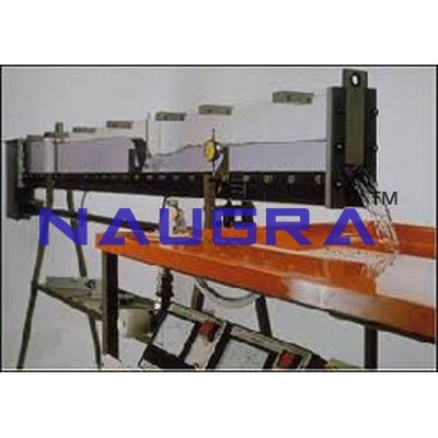
Flow Channels (section: 80 x 300 mm).(several lengths) EXERCISES AND PRACTICAL POSSIBILITIES Some Practical Possibilities of the Unit: (in function of the accessories used) 1.-Measurement of the water height and the velocity along the channel. 2.-Measurement of the flow with weirs of thin wall. 3.-Measurement of flow with changes in the channel section. 4.-Measurement of flow using Venturi flume. 5.-Control of the flow by gates. 6.-Level control using syphons. 7.-Flow on overflow dams. 8.-Flow among the pillars of a bridge. 9.-Connection of a channel to a culvert. 10.-Characterization of the hydraulic jump. 11.-Profiles of the water free surface. 12.-Investigation of flow and supercritical flow states. 13.-Measurement of water levels. 14.-Discharge processes on an underwater weir. 15.-Amount of energy in flows in open channels. 16.-Function of a syphon weir. 17.-Flow rate and drain coefficients of a syphon weir. 18.-Pipe flows. 19.-Comparison of overflow and syphon weirs. 20.-Observation of the throw of the water. 21.-Generation of different flow states by damming the down-stream water. 22.-Observation of the flow under an undershot weir: -Observation of hydraulic motion on discharge. 23.-Relationship between dam height and discharge. 24.-Observation of discharges under a radial gate -Observation of hydraulic motion on discharge. 25.-Hydrostatic pressure on a weir. 26.-Investigations on waves. 27.-Behaviour of structures in rough sea. 28.-Applying and understanding Manning’s formula. 29.-Understanding sub- and super-critical flow. 30.-Learning how to apply force-momentum and steady flow energy equations to simple flow situations. 31.-Investigation of the transition from running to shooting flow. Other possible practices: 32.-Filling of the Pitot tube. 33.-Filling of the venturi meter with analog output. 34.-Filling of the manometric tubes. 35.-Calculation of water flow. 36.-Use of level gauge for measurement of the water height. Fluid Mechanics Lab Equipments manufacturers...
Computer Controlled Flow Channels (section: 300 x 450mm). (several lengths) EXERCISES AND PRACTICAL POSSIBILITIES Some Practical Possibilities of the unit: (in function of the accessories used) 1.-Measurement of the water height and the velocity along the channel. 2.-Measurement of the flow with weirs of thin wall. 3.-Measurement of flow with changes in the channel section. 4.-Measurement of flow using Venturi flume. 5.-Control of the flow by gates. 6.- Level control using syphons. 7.-Flow on overflow dams. 8.- Flow among the pillars of a bridge. 9.- Connection of a channel to a culvert. 10.-Characterization of the hydraulic jump. 11.-Profiles of the water free surface. 12.-Investigation of flow and supercritical flow states. 13.-Measurement of water levels. 14.-Discharge processes on an underwater weir. 15.-Amount of energy in flows in open channels. 16.-Function of a syphon weir. 17.-Flow rate and drain coefficients of a syphon weir. 18.-Pipe flows. 19.-Comparison of overflow and syphon weirs. 20.-Observation of the throw of the water. 21.-Generation of different flow states by damming the down-stream water. 22.-Observation of the flow under an undershot weir: -Observation of hydraulic motion on discharge. 23.-Relationship between dam height and discharge. 24.-Observation of discharges under a radial gate -Observation of hydraulic motion on discharge. 25.-Hydrostatic pressure on a weir. 26.-Investigations on waves. 27.-Behaviour of structures in rough sea. 28.-Applying and understanding Manning’s formula. 29.-Understanding sub- and super-critical flow. 30.-Learning how to apply force-momentum and steady flow energy equations to simple flow situations. 31.-Investigation of the transition from running to shooting flow. Other possible practices: 32.-Filling of the Pitot tube. 33.-Filling of the venturi meter with analog output. 34.-Calculation of water flow. 35.- Use of level gauge for measurement of the water height. Fluid Mechanics Lab Equipments manufacturers...
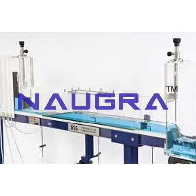
EXERCISES AND PRACTICAL POSSIBILITIES Some Practical Possibilities of the Unit: (in function of the accessories used) 1.-Measurement of the water height and the velocity along the channel. 2.-Measurement of the flow with weirs of thin wall. 3.-Measurement of flow with changes in the channel section. 4.-Measurement of flow using Venturi flume. 5.-Control of the flow by gates. 6.-Level control using syphons. 7.-Flow on overflow dams. 8.-Flow among the pillars of a bridge. 9.-Connection of a channel to a culvert. 10.-Characterization of the hydraulic jump. 11.-Profiles of the water free surface. 12.-Investigation of flow and supercritical flow states. 13.-Measurement of water levels. 14.-Discharge processes on an underwater weir. 15.-Amount of energy in flows in open channels. 16.-Function of a syphon weir. 17.-Flow rate and drain coefficients of a syphon weir. 18.-Pipe flows. 19.-Comparison of overflow and syphon weirs. 20.-Observation of the throw of the water. 21.-Generation of different flow states by damming the down-stream water. 22.-Observation of the flow under an undershot weir: -Observation of hydraulic motion on discharge. 23.-Relationship between dam height and discharge. 24.-Observation of discharges under a radial gate: -Observation of hydraulic motion on discharge. 25.-Hydrostatic pressure on a weir. 26.-Investigations on waves. 27.-Behaviour of structures in rough sea. 28.-Applying and understanding Manning’s formula. 29.-Understanding sub- and super-critical flow. 30.-Learning how to apply force-momentum and steady flow energy equations to simple flow situations. 31.-Investigation of the transition from running to shooting flow. Other possible practices: 32.-Filling of the Pitot tube. 33.-Filling of the venturi meter with analog output. 34.-Calculation of water flow. 35.-Use of level gauge for measurement of the water height. Fluid Mechanics Lab Equipments manufacturers...
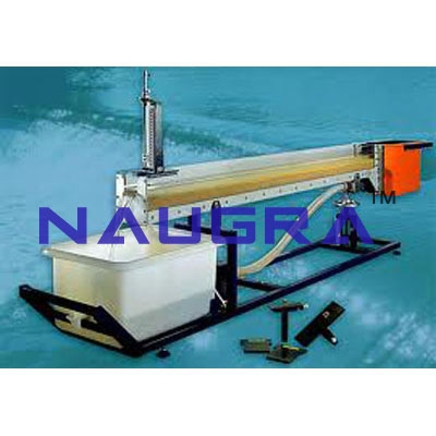
EXERCISES AND PRACTICAL POSSIBILITIES Some Practical Possibilities of the Unit: Flow over a mobile sand-bed (bedforms associated with increasing flow intensity and sediment transport rate) 1.- Lower Regime (bedforms exhibed): - Plane- bed (no motion). - Ripples and dunes. - Washed-out dunes. -Ripples. -Dunes. 2.- Upper Regime(bedforms exhibed): - Plane- bed (with motion). - Chutes and pools. - Anti- dunes. - Breaking anti-dunes. - Standing waves. Flow over fixed, gravel-bed 3.- Although the channel can not transport gravel, this can be used to investigate flow resistance in gravel and polder- bed rivers. 4.- We can calculate the flow resistance coeficients, using equations such as those of Bray, Limerinos, Hey, Lacey, Thompson and Campbell and Bathurst and the results compared to the actual values obtained by observation. Flow structures 5.- We can examine the structure of turbulence in the flow, using dye injection, interesting for the dune bedform configuration and clearly demonstrates separation on the lee face. Fixed, smooth bed flow (the channel may be used without sediment on the bed to demonstrate several flow phenomena and equations) 6.- Rapid, super- critical flow- dominance of intertial over gravity forces, shock waves from flow obstructions. 7.- Turbulence. 8.- Governing equations of open channel flow-Reynold’s number, Froude number, continuity, Bernoulli’s equation, weir equations. 9.- Tranquil, sub-critical flow- movement of surface waves upstream against flow. 10.-Hydraulic jump- transition from super to sub critical flow, air entrainment, mixing. 11.-Flow measurement- using sharp crested weirs. Bedform hysteresis 12.-If the discharge in the channel changes quickly, there is no sufficient time for bedforms to adjust to the new flow regime. Hence, if a flood hydrograph is simulated by increasing and then decreasing the discharge, different depths will occur for the same discharge on the rising and falling limbs. Data collection and numerical evaluation(computational work) 13.-In addition to illustrating flow and sediment phenomena, we can use the channel for basic data collection and numerical evaluation of the following: - Flow resistance: Manning, Chezy and Darcy-Weisbach fricion factors for several bedform configuration. Fluid Mechanics Lab Equipments manufacturers...
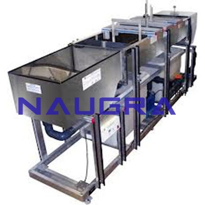
EXERCISES AND PRACTICAL POSSIBILITIES 1.-Flow around model engineering structures. 2.-Mobile bed experiments. 3.-Meandering water courses characteristics. 4.-Visualization of the behaviour of boundary layers. 5.-Demonstration of boundary layer suction. 6.-Experiments of erosion. 7.-Experiments of deposition. 8.-Velocity distribution in duct flow. 9.-Practices and tests with models for engineering. 10.-Two dimensional flow visualization by the Ahlborn tecnique. 11.- Hydraulic analogy to compressible flow. 12.- Sediment erosion and deposits. Fluid Mechanics Lab Equipments manufacturers...
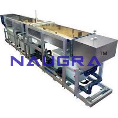
EXERCISES AND PRACTICAL POSSIBILITIES 1.-Flow around model engineering structures. 2.-Mobile bed experiments. 3.-Meandering water courses characteristics. 4.-Visualization of the behaviour of boundary layers. 5.-Demonstration of boundary layer suction. 6.-Experiments of erosion. 7.-Experiments of deposition. 8.-Velocity distribution in duct flow. 9.-Practices and tests with models for engineering. 10.-Two dimensional flow visualization by the Ahlborn tecnique. 11.-Hydraulic analogy to compressible flow. 12.-Sediment erosion and deposits. Fluid Mechanics Lab Equipments manufacturers...
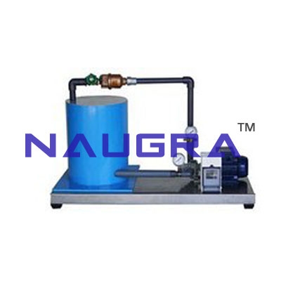
Exercises and Practical Possibilities to be done with Main Items 1.-Determination of the flow by a weir of thin wall in U-shape. 2.-Determination of unloading coefficient of a weir of thin wall in a U-shape. 3.-Determination of the curve Q vs r.p.m. for the centrifugal pump. 4.-Determination of the curve Q vs r.p.m. for the peripherical pump. 5.-Determination of the curve Q vs r.p.m. for the gear pump. 6.-Determination of the curve Q vs r.p.m. for the axial pump. 7.-Determination of the curve H vs Q for different r.p.m. for the centrifugal pump. 8.-Determination of the curve H vs Q for different r.p.m. for the peripherical pump. 9.-Determination of the curve H vs Q for different r.p.m. for the gear pump. 10.-Determination of the curve H vs Q for different r.p.m. for the axial pump. 11.-Determination of the mechanical power vs flow for different r.p.m. for the centrifugal pump. 12.-Determination of the mechanical power vs flow for different r.p.m. for the gear pump. 13.-Determination of the mechanical power vs flow for different r.p.m. for the peripherical pump. 14.-Determination of the mechanical power vs flow for different r.p.m. for the axial pump. 15.-Determination of the curve h vs the flow for different r.p.m. for the centrifugal pump. 16.-Determination of the curve h vs the flow for different r.p.m. for the peripherical pump. 17.-Determination of the curve h vs the flow for different r.p.m. for the gear pump. 18.-Determination of the curve h vs the flow for different r.p.m. for the axial pump. 19.-Determination of the map of a centrifugal pump. 20.-Determination of the map of a peripherical pump. 21.-Determination of the map of a gear pump. 22.-Determination of the map of an axial pump. 23.-Determination of the adimenssional characteristic curves for different types of pumps. 24.-Determination of the specific speed of different types of pumps. 25.-Verification of the similarity rules for pumps of different geometry. Additional practical possibilities: 26.-Sensors calibration. Other possibilities to be done with this Unit: 27.-Many students view results simultaneously. To view all results in real time in the classroom by means of a projector or an electronic blackboard. 28.-Open Control, Multicontrol and Real Time Control. This unit allows intrinsically and/or extrinsically to change the span, gains; proportional, integral, derivate parameters; etc in real time. 29.-The Computer Control System with SCADA allows a real industrial simulation. 30.-This unit is totally safe as uses mechanical, electrical and electronic, and software safety devices. 31.-This unit can be used for doing applied research. 32.-This unit can be used for giving training courses to Industries even to other Technical Education Institutions. 33.-Control of the PBOC unit process through the control interface box without the computer. 34.-Visualization of all the sensors values used in the PBOC unit process. - By using PLC-PI additional 19 more exercises can be done. - Several other exercises can be done and designed by the user. Fluid Mechanics Lab Equipments manufacturers...
Exercises and Practical Possibilities to be done with Main Items 1.-Determination of the flow by a weir of thin wall in a U-shape. 2.-Determination of the unloading coefficient of a weir of thin wall in a U-shape. 3.-Determination of the curve Q vs r.p.m. for the centrifugal pump. 4.-Determination of the curve Q vs r.p.m. for the gear pump. 5.-Determination of the curve H vs Q for different r.p.m. for the centrifugal pump. 6.-Determination of the curve H vs Q for different r.p.m. for the gear pump. 7.-Determination of the mechanical power vs flow for different r.p.m. for the centrifugal pump. 8.-Determination of the mechanical power vs flow for different r.p.m. for the gear pump. 9.-Determination of the curve h vs the flow for different r.p.m. for the centrifugal pump. 10.-Determination of the curve h vs the flow for different r.p.m. for the gear pump. 11.-Determination of the map of a centrifugal pump. 12.-Determination of the map of a gear pump. 13.-Determination of the adimensional characteristic curves for the different pumps. 14.-Determination of the specific speed for the different pumps. 15.-Verification of the similarity rules for pumps of different geometry. Additional practical possibilities: 16.-Sensors calibration. Other possibilities to be done with this Unit: 17.-Many students view results simultaneously. To view all results in real time in the classroom by means of a projector or an electronic blackboard. 18.-Open Control, Multicontrol and Real Time Control. This unit allows intrinsically and/or extrinsically to change the span, gains; proportional, integral, derivate parameters; etc in real time. 19.-The Computer Control System with SCADA allows a real industrial simulation. 20.-This unit is totally safe as uses mechanical, electrical and electronic, and software safety devices. 21.-This unit can be used for doing applied research. 22.-This unit can be used for giving training courses to Industries even to other Technical Education Institutions. 23.-Control of the PB2C unit process through the control interface box without the computer. 24.-Visualization of all the sensors values used in the PB2C unit process. - By using PLC-PI additional 19 more exercises can be done. - Several other exercises can be done and designed by the user. Fluid Mechanics Lab Equipments manufacturers...
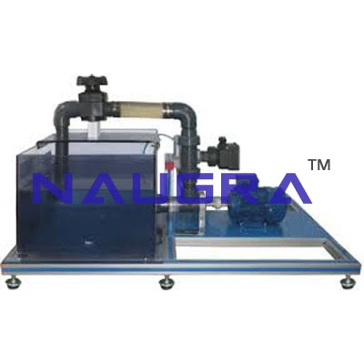
Exercises and Practical Possibilities to be done with Main Items 1.-Demonstration of a centrifugal water pump in operation. 2.-Introduction to pump speed laws. 3.-Obtaining of curves H(Q), N(Q) and Eff%(Q). 4.-Simultaneous representation of H(Q), N(Q) and Eff%(Q). 5.-Obtaining the map of a centrifugal pump. 6.-Adimensional study of magnitudes H *, N * and Q *. 7.-Cavitation test and obtaining of curves NPSHr. Additional practical possibilities: 8.-Sensors calibration. Other possibilities to be done with this Unit: 9.-Many students view results simultaneously. To view all results in real time in the classroom by means of a projector or an electronic blackboard. 10.-Open Control, Multicontrol and Real Time Control. This unit allows intrinsically and/or extrinsically to change the span, gains; proportional, integral, derivate parameters; etc in real time. 11.-The Computer Control System with SCADA allows a real industrial simulation. 12.-This unit is totally safe as uses mechanical, electrical and electronic, and software safety devices. 13.-This unit can be used for doing applied research. 14.-This unit can be used for giving training courses to Industries even to other Technical Education Institutions. 15.-Control of the PBCC unit process through the control interface box without the computer. 16.-Visualization of all the sensors values used in the PBCC unit process. - By using PLC-PI additional 19 more exercises can be done. - Several other exercises can be done and designed by the user....
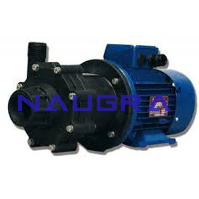
EXERCISES AND PRACTICAL POSSIBILITIES Some Practical Possibilities of the Unit: 1.-Demonstration of a centrifugal water pump in operation. 2.-Introduction to pump speed laws. 3.-Obtaining of curves H(Q), N(Q) and Eff%(Q). 4.-Obtaining of the map of a centrifugal pump. 5.-Adimensional study of magnitudes H *, N * and Q *. 6.-Cavitation test and obtaining of curves NPSHr. Fluid Mechanics Lab Equipments manufacturers...
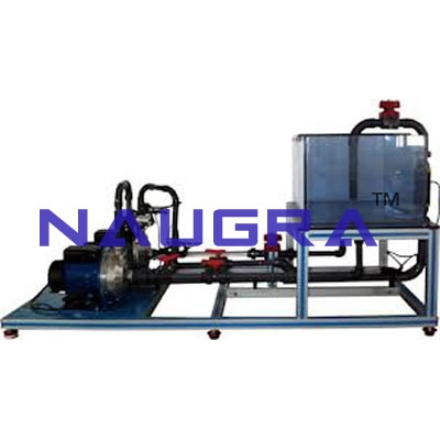
Exercises and Practical Possibilities to be done with Main Items 1.-Obtaining of curves H (Q), N (Q), Eff% (Q). 2.-Three simultaneous representatios of H (Q), N (Q) and Eff% (Q). 3.-Obtaining of the map of a centrifugal pump. 4.-Adimensional study of magnitudes H*, N* and Q*. 5.-Cavitation test and obtaining of curves NPSHr. 6.-Series coupling of two pumps with same characteristics. 7.-Series coupling of two pumps of different characteristics. 8.-Parallel coupling of two pumps with same characteristics. 9.-Parallel coupling of two pumps of different characteristics. Additional practical possibilities: 10.-Sensors calibration. Other possibilities to be done with this Unit: 11.-Many students view results simultaneously. To view all results in real time in the classroom by means of a projector or an electronic blackboard. 12.-Open Control, Multicontrol and Real Time Control. This unit allows intrinsically and/or extrinsically to change the span, gains; proportional, integral, derivate parameters; etc in real time. 13.-The Computer Control System with SCADA allows a real industrial simulation. 14.-This unit is totally safe as uses mechanical, electrical and electronic, and software safety devices. 15.-This unit can be used for doing applied research. 16.-This unit can be used for giving training courses to Industries even to other Technical Education Institutions. 17.-Control of the PBSPC unit process through the control interface box without the computer. 18.-Visualization of all the sensors values used in the PBSPC unit process. - By using PLC-PI additional 19 more exercises can be done. - Several other exercises can be done and designed by the user. Fluid Mechanics Lab Equipments manufacturers...
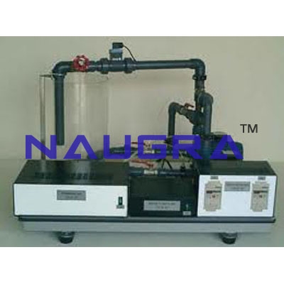
EXERCISES AND PRACTICAL POSSIBILITIES Some Practical Possibilities of the Unit: 1.-Obtaining of curves H (Q), N (Q), Eff% (Q). 2.-Obtaining of the map of a centrifugal pump. 3.-Adimensional study of magnitudes H*, N* and Q*. 4.-Cavitation test and obtaining of curves NPSHr. 5.-Series coupling of two pumps with same characteristics. 6.-Series coupling of two pumps of different characteristics. 7.-Parallel coupling of two pumps with same characteristics. 8.-Parallel coupling of two pumps of different characteristics. Fluid Mechanics Lab Equipments manufacturers...
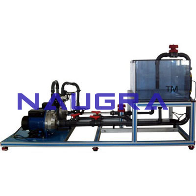
EXERCISES AND PRACTICAL POSSIBILITIES
Some Practical Possibilities of the Unit:
1.-Demonstration of a gear pump in operation.
2.-Obtaining of curves H(Q), N(Q), Efficiency (Q) of the gear pump.
3.-Simultaneous representation of H(Q), N(Q) and Efficiency (Q).
4.-Adimensional study of magnitudes H*, N* and Q*.
5.-Determination of the curve H vs Q at different r.p.m.
6.-Determination of the mechanical power vs flow at different r.p.m.
7.-Determination of the efficiency curve vs the flow at different r.p.m.
8.-Determination of the map of a gear pump.
Other possible practices:
9.-Sensors Calibration.
Practices to be done by PLC Module (PLC-PI)+PLC Control Software:
10.-Control of the PBEC unit process through the control interface box without the computer.
11.-Visualization of all the sensors values used in the PBEC unit process.
12.-Calibration of all sensors included in the PBEC unit process.
13.-Hand on of all the actuators involved in the PBEC unit process.
14.-Realization of different experiments, in automatic way, without having in front the unit. (This experiment can be decided previously).
15.-Simulation of outside actions, in the cases do
not
exist hardware elements. (Example: test of complementary tanks,
complementary industrial environment to the process to be studied, etc).
16.-PLC hardware general use and manipulation.
17.-PLC process application for PBEC unit.
18.-PLC structure.
19.-PLC inputs and outputs configuration.
20.-PLC configuration possibilities.
21.-PLC program languages.
22.-PLC different programming standard languages.
23.-New configuration and development of new process.
24.-Hand on an established process.
25.-To visualize and see the results and to make comparisons with the PBEC unit process.
26.-Possibility of creating new process in relation with the PBEC unit.
27.-PLC Programming Exercises.
28.-Own PLC applications in accordance with teacher and student requirements. Fluid Mechanics Lab Equipments manufacturers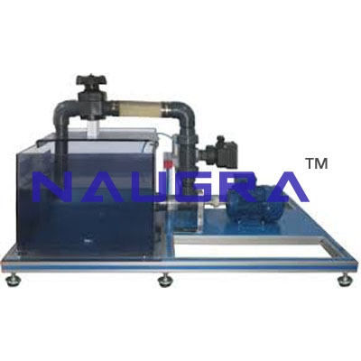
Exercises and Practical Possibilities to be done with Main Items 1.-Determination of the Q vs. r.p.m. curve for an axial pump. 2.-Determination of the H vs. Q curve for different r.p.m. of an axial pump. 3.-Determination of the mechanical power vs flow for different r.p.m. of an axial pump. 4.-Determination of the h vs flow curve for different r.p.m. of an axial pump. 5.-Determination of an axial pump’s map. Other additional practical possibilities: 6.-Sensors calibration. 7.-Obtaining the H(n) and N(n) curves. 8.-Study of the influence of pressure at the outlet. 9.-Calculation of the axial pump efficiency. Other possibilities to be done with this Unit: 10.-Many students view results simultaneously. To view all results in real time in the classroom by means of a projector or an electronic blackboard. 11.- Open Control, Multicontrol and Real Time Control. This unit allows intrinsically and/or extrinsically to change the span, gain; proportional, integral, derivate parameters; etc, in real time. 12.-The Computer Control System with SCADA allows a real industrial simulation. 13.-This unit is totally safe as uses mechanical, electrical and electronic, and software safety devices. 14.-This unit can be used for doing applied research. 15.-This unit can be used for giving training courses to Industries even to other Technical Education Institutions. 16.-Control of the PBAC unit process through the control interface box without the computer. 17.-Visualization of all the sensors values used in the PBAC unit process. - By using PLC-PI additional 19 more exercises can be done. - Several other exercises can be done and designed by the user. Fluid Mechanics Lab Equipments manufacturers...
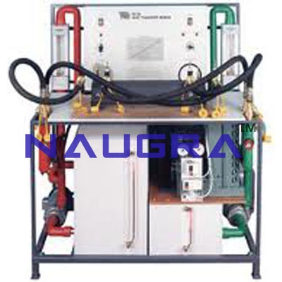
EXERCISES AND PRACTICAL POSSIBILITIES Some Practical Possibilities of the Unit: 1.- Demonstration of a piston pump in operation. 2.- Measurement of plunger displacement. 3.- Measurement of cylinder pressure. 4.- Measurement of pump outlet pressure. 5.- Measurement of the volumetric efficiency. 6.- Obtain the curves of the pump H(n), N(n). 7.- Obtain the pump map. 8.- Study of safety valve for overpressure in operation. 9.- Study of the pressures influence at the exit when the piston pump works with a damping chamber. 10.-Pump efficiency calculation. 11.-Study of the effect to incorporate the damping chamber. Other possible practices: 12.-Sensors calibration. Practices to be done by PLC Module (PLC-PI)+PLC Control Software: 13.-Control of the PBRC unit process through the control interface box without the computer. 14.-Visualization of all the sensors values used in the PBRC unit process. 15.-Calibration of all sensors included in the PBRC unit process. 16.-Hand on of all the actuators involved in the PBRC unit process. 17.-Realization of different experiments, in automatic way, without having in front the unit. (This experiment can be decided previously). 18.-Simulation of outside actions, in the cases do not exist hardware elements. (Example: test of complementary tanks, complementary industrial environment to the process to be studied, etc). 19.-PLC hardware general use and manipulation. 20.-PLC process application for PBRC unit. 21.-PLC structure. 22.-PLC inputs and outputs configuration. 23.-PLC configuration possibilities. 24.-PLC program languages. 25.-PLC different programming standard languages (literal structured, graphic, etc.). 26.-New configuration and development of new process. 27.-Hand on an established process. 28.-To visualize and see the results and to make comparisons with the PBRC unit process. 29.-Possibility of creating new process in relation with the PBRC unit. 30.-PLC Programming Exercises. 31.-Own PLC applications in accordance with teacher and student requirements. Fluid Mechanics Lab Equipments manufacturers...
As leading Didactic Lab Equipment Suppliers and School Lab Equipment Manufacturers in India, we specialise in bulk tender supply for Ministry of Education projects, TVET institutes, polytechnics, engineering colleges and research universities. Our Fluid Mechanics meet international quality standards and are exported to 100+ countries including Africa, Middle East, Southeast Asia, Latin America and the CIS region.
Every order ships with technical documentation, installation support, training materials and a manufacturer warranty. We accept LC, T/T and MOE tender payment terms. Request a customised quotation for your school lab, college lab, polytechnic or vocational training centre today.