
Channel PAM PCM
Channel PAM PCM Manufacturer, Exporter & Bulk Supplier from India for School Lab Equipment, TVET Tender & MOE Projects.
- Exported to 100+ Countries
- Made in India · Factory Direct
- MOE Tender & LC Payments Accepted
- For Schools, Colleges, TVET, Polytechnics
Product Description
Channel PAM PCM is manufactured by Didactic Lab Equipments, a leading School Lab Equipment Manufacturer in India serving Ministry of Education tenders, vocational training centres, polytechnics and engineering colleges across 100+ countries. Buy Channel PAM PCM at factory-direct prices with full technical support.
Technical Specification
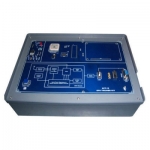
Interactive Practical Electronics System – I.P.E.S.
It consists of a set of components and circuits for performing experiments.
The lessons included in this module can be developed in:
- Standard mode: using the switches of the equipment and
consulting the handbook;
- Computerized mode: the interactive software version of
the handbook - interfaced to the module
via Control Unit , is used. This software inserts circuit
variations and faults automatically enabling the development
of lessons even without teacher’s assistance.
TRAINING PROGRAM
Analog signal sampling: sampling theorem, sampled
signal spectrum, sampling frequency
• Reconstruction of the analog signal starting from
samples
• Pulse modulation:
- PAM (Pulse Amplitude Modulation)
- PPM (Pulse Position Modulation)
- PWM (Pulse Width Modulation)
• Signal digital coding: PCM/DELTA
• Time division multiplexing (TDM) of PAM and PCM signals
• Communication systems using PAM, PPM, PWM, Linear
and Adaptive DELTA, PCM, multi-channel PAM and PCM
• Optimum sampling point in reception
• Effects of the transmission medium and noise
• Voice transmission
• Troubleshooting
TECHNICAL SPECIFICATION:
• Sampling frequency: 8 kHz
• Low-pass filters: active, 4-pole; cut-off frequency 3.4 kHz
• PLL reception clock recovery
• Signal sampler in reception: with adjustment of the
sampling pulse phase
• 2 PCM CODECs with “A” and “μ” coding
• 2 CVSD with syllabic filter: 16- and 32-kHz clock frequency
• Channel simulator: adjustable attenuation and bandwidth
(5/10/20/40/100 kHz)
• Noise generator: adjustable amplitude
• 1-kHz synchronous generator with clocks, for easier wave
form examination
• Microphone and loudspeaker: included
• Fault simulation: Possibility to insert 10 faults
• Test and interconnection points, Ø 2 mm
• Rapid modifications to circuits using jumpers
37-pin connector to the fault insertion unit
• 8-wire connector to the power supply unit
• Printed circuit board with protective treatment and mimic
diagram
• Module equipped with ABS protection on its lower side
Bulk Tender Supply & Worldwide Export
- Bulk MOQ pricing for tenders & institutional orders
- Custom branding & private-label available
- CIF / FOB / Door-to-door delivery worldwide
- Letter of Credit, T/T, MOE tender payment terms
- Installation, commissioning & training support
- Manufacturer warranty & after-sales service
Related Lab Equipment
Why Buy Channel PAM PCM from Didactic Lab Equipments?
As one of India's leading Didactic Lab Equipment Suppliers and School Lab Equipment Manufacturers, we supply Channel PAM PCM in bulk for educational tenders, MOE projects, TVET training centres, polytechnics, engineering colleges and research universities worldwide. Our manufacturing facility in Ambala (Haryana, India) ships to 100+ countries with factory-direct pricing.
Looking for Channel PAM PCM in bulk for school lab tenders, college lab supply or vocational training centres? Our team handles the complete tender cycle — technical specifications, pre-shipment inspection, FOB/CIF logistics and after-sales support. Request a customised quotation today.