
Coding 7AMI/HDB3/CMIDATA Terster
Coding 7AMI/HDB3/CMIDATA Terster Manufacturer, Exporter & Bulk Supplier from India for School Lab Equipment, TVET Tender & MOE Projects.
- Exported to 100+ Countries
- Made in India · Factory Direct
- MOE Tender & LC Payments Accepted
- For Schools, Colleges, TVET, Polytechnics
Product Description
Coding 7AMI/HDB3/CMIDATA Terster is manufactured by Didactic Lab Equipments, a leading School Lab Equipment Manufacturer in India serving Ministry of Education tenders, vocational training centres, polytechnics and engineering colleges across 100+ countries. Buy Coding 7AMI/HDB3/CMIDATA Terster at factory-direct prices with full technical support.
Technical Specification
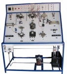
MCM33/EV is one of the experiment boards that constitute the
Interactive Practical Electronics System – I.P.E.S.
It consists of a set of components and circuits for performing experiments.
The lessons included in this module can be developed in:
- Standard mode: using the switches of the equipment and
consulting the handbook;
- Computerized mode: the interactive software version of
the handbook - interfaced to the module
via Control unit, is used. This software inserts circuit
variations and faults automatically enabling the development
of lessons even without teacher’s assistance.
TRAINING PROGRAM:
• Discrete input source
• Channel coding (error control)
• Line coding and precoding importance
• Transmission and reception filter (spectrum modeling)
• Effects of the characteristic of the transmission line
• Intersymbol interference
• Eye diagram
• Data extraction
• Synchronism recovery
• Sampling of the received signaling pulses
• Error rate calculation
• Analysis of the Fourier spectrum of the signal present in the
main points of the transmission and reception system, to
observe the characterization and the
modifications of the
same spectrum
• Digital Signal Processing: description of the schematic
diagram and operating modes of a specific microprocessor
for digital signal processing
• Troubleshooting
TECHNICAL SPECIFICATION:
• Discrete input generator
• Channel encoder and decoder with cyclic redundancy code
• Line encoder and decoder with section of:
- precoding: differential, scrambling, 3B-4B
- coding: NRZ, RZ, CMI, HDB3, Manchester, MLT-3,
2B-1Q, 2-binary
• 10 LED’s indicating precoding and line coding
• Transmission and reception filter (spectrum modeling)
• Transmission line simulator: band width, attenuation and
variable noise generator
• Timing circuits, numeric processing and
filtering with FPGA
and DSP devices
• BER measurements: bar LED’s on the display indicating lost
blocks and recovered blocks
Spectrum display: TX/RX signals after the transmission line
with LCD graphic display 160x128 dot pixels
• Fault simulation: Possibility to insert 10 faults
• Test and interconnection points, Ø 2 mm
• Rapid modifications to circuits using jumpers
• 37-pin connector to the fault insertion unit
• 8-wire connector to the power supply unit
• Printed circuit board with protective treatment and mimic
diagram
• Module equipped with ABS protection on its lower side
Bulk Tender Supply & Worldwide Export
- Bulk MOQ pricing for tenders & institutional orders
- Custom branding & private-label available
- CIF / FOB / Door-to-door delivery worldwide
- Letter of Credit, T/T, MOE tender payment terms
- Installation, commissioning & training support
- Manufacturer warranty & after-sales service
Related Lab Equipment
Why Buy Coding 7AMI/HDB3/CMIDATA Terster from Didactic Lab Equipments?
As one of India's leading Didactic Lab Equipment Suppliers and School Lab Equipment Manufacturers, we supply Coding 7AMI/HDB3/CMIDATA Terster in bulk for educational tenders, MOE projects, TVET training centres, polytechnics, engineering colleges and research universities worldwide. Our manufacturing facility in Ambala (Haryana, India) ships to 100+ countries with factory-direct pricing.
Looking for Coding 7AMI/HDB3/CMIDATA Terster in bulk for school lab tenders, college lab supply or vocational training centres? Our team handles the complete tender cycle — technical specifications, pre-shipment inspection, FOB/CIF logistics and after-sales support. Request a customised quotation today.