- Civil Lab Mechanical Lab Engineering Lab Equipments
- sales@didacticlabequipments.com

CAT NO: DIDACTICNSSE0058
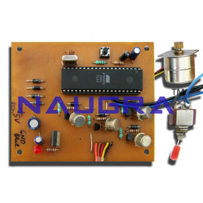
Control of Stepper Motor Using Microcontroller.
Control of Stepper motor using microcontroller At the heart of the Stepper Motor Controller is AT89C51
micro-controller. From traffic control equipment to input devices, computer
networking products and stepper motor controllers, 89C51 microcontrollers
deliver a high performance with a choice of configurations and options matched
to the specific needs of each application.
In the Stepper Motor Controller circuit, the control switches for the motor are
connected to Reset and Port P0.7 pins of the microcontroller while the stepper
motor is connected to port pins P2.4 through P2.7 of the microcontroller (IC2)
through the motor-driver circuit consisting of four Darlington pairs comprising
transistors BC548 and SL100 (T1-T2, T3-T4, T5-T6 and T7-T8).
When transistors conduct, 5V (Vcc) is applied to the coils of the motor and the
currents flowing through them create magnetic fields and the motor starts
rotating. The magnetic field energy thus created is stored in the coils.
When transistors stop conducting, power to the coils is cut off, the magnetic
field collapses and a reverse voltage (called inductive kickback or back emf)
is generated in the coils. The back emf can be more than 100 volts. The diodes
connected across the coils absorb the reverse voltage spike.
