
Digital Lab For Electrical Lab Training
Digital Lab For Electrical Lab Training Manufacturer, Exporter & Bulk Supplier from India for School Lab Equipment, TVET Tender & MOE Projects.
- Exported to 100+ Countries
- Made in India · Factory Direct
- MOE Tender & LC Payments Accepted
- For Schools, Colleges, TVET, Polytechnics
Product Description
Digital Lab For Electrical Lab Training is manufactured by Didactic Lab Equipments, a leading School Lab Equipment Manufacturer in India serving Ministry of Education tenders, vocational training centres, polytechnics and engineering colleges across 100+ countries. Buy Digital Lab For Electrical Lab Training at factory-direct prices with full technical support.
Technical Specification
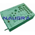
The digital lab covers regular digital circuits by solder-less interconnections on breadboard and as well as compatible with all optional modules through use of 2mm brass terminals and patch cords. Various clock generators, logic level input/output indicators and DC regulated power supplies etc. are in-built. The unit housed in attractive enclosure is supplied with mains cord, patch cords, Instruction manual and Component Set. Experimental Coverage: Logic gates operation To verify De-morgan’s theorem with boolean logic equations Binary to Gray code conversion Gray code to Binary conversion Binary to Excess-3 code conversion Binary Adder and Subtractor Binary Multiplier EX-OR gate implementation Application of EX-OR gate Johnson Counter To verify the dual nature of Logic Gates Study of Flip-Flops RS, JK, D&T Multiplexer and Demultiplexer 4 Bit Binary up and down counter Study of 8 to 3 Line Encoder Study of 3 to 8 Line Decoder Study of Shift Register (SIPO) CMOS-TTL Interfacing Study of Crystal oscillator Study of pulse stretcher circuit Features: Bread Board : Unique solder-less large size, spring loaded breadboard consisting of two Terminal Strips with 1280 tie points and 4 Distribution Strips with 100 tie points each, totaling to 1680 tie points. (Size : 112mm x 170mm approx) Regulated DC Power Supply : +5V at 1 Amp, -5V at 500 mA, 3 to +15V at 500mA, and -3 to -15V at 500 mA. Pulse Generator : 1 Hz to 1 MHz in 6 Steps. Variable in between steps - Amplitude : 3-15V (CMOS), 5V (TTL) - Duty Cycle : 50% TTL / CMOS Output Pulsar Switches : 2 independent buffered bounce free manual pulser (useful for freezing the action of each stage of the counter after every clock pulse) Data Switches : 12 Nos. independent buffered logic level inputs to select High / Low TTL levels, each with a bi-color LED to indicate high / low status and termination. Logic Indicators : 12 Nos. independent buffered logic level indicators for High / Low status indication with bi-color LED for digital outputs Seven Segment Display : 2 Nos. BCD to Seven Segment Decoder / Driver IC with terminals Logic Probe : Logic level indicator for TTL / CMOS CMOS/TTL : Provided Power : 230 V ± 10%, 50 Hz Components Provided : ICs-4001/1, 4049/1,4069/1, 7400/1, 7402/1, 7404/1, 7406/1, 7408/2, 7410/2, 7411/3, 7420/2,7432/3, 7474/2,7476/2,7486/1.Resistors-330E/1,1K/2, 1K8/1,,15K/1, 47K/1.1M/2, Capacitors- 0.01mF/1, 0.1mF/1, 0.22 mF/1,Crystal-32.768MHz/1. Accessories : Mains cord, Operating and Experimental manual, Red & Black patch cords (2mm with Pin) 10 each, Red & Black patch cord (Pin to Pin) 10 each. Wire 24/25 SWG. 1Meter each 5 Color Instruction manual : Strongly supported by detailed operating instructions. Weight : 5 Kg. (Approx.) Dimension : W 412 x H 150 x D 310
The Digital Lab is intended for
elementary as well as advance training of digital electronics.
Bulk Tender Supply & Worldwide Export
- Bulk MOQ pricing for tenders & institutional orders
- Custom branding & private-label available
- CIF / FOB / Door-to-door delivery worldwide
- Letter of Credit, T/T, MOE tender payment terms
- Installation, commissioning & training support
- Manufacturer warranty & after-sales service
Related Lab Equipment

.jpg)
Why Buy Digital Lab For Electrical Lab Training from Didactic Lab Equipments?
As one of India's leading Didactic Lab Equipment Suppliers and School Lab Equipment Manufacturers, we supply Digital Lab For Electrical Lab Training in bulk for educational tenders, MOE projects, TVET training centres, polytechnics, engineering colleges and research universities worldwide. Our manufacturing facility in Ambala (Haryana, India) ships to 100+ countries with factory-direct pricing.
Looking for Digital Lab For Electrical Lab Training in bulk for school lab tenders, college lab supply or vocational training centres? Our team handles the complete tender cycle — technical specifications, pre-shipment inspection, FOB/CIF logistics and after-sales support. Request a customised quotation today.