
Digital Modulation
Digital Modulation Manufacturer, Exporter & Bulk Supplier from India for School Lab Equipment, TVET Tender & MOE Projects.
- Exported to 100+ Countries
- Made in India · Factory Direct
- MOE Tender & LC Payments Accepted
- For Schools, Colleges, TVET, Polytechnics
Product Description
Digital Modulation is manufactured by Didactic Lab Equipments, a leading School Lab Equipment Manufacturer in India serving Ministry of Education tenders, vocational training centres, polytechnics and engineering colleges across 100+ countries. Buy Digital Modulation at factory-direct prices with full technical support.
Technical Specification
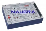
Experiment board for the study of digital modulation transmitters
and receivers: ASK (Amplitude Shift Keying), FSK (Frequency
Shift Keying), PSK (Phase Shift Keying), QPSK (Quadrature Phase
Shift Keying) and QAM (Quadrature Amplitude Modulation). It
contains all the pre-assembled electronic components needed
to construct the experiment circuits and divided into functional
blocks which can be interconnected and modifi ed by means of
supplied jumpers and connection cables.
TRAINING PROGRAM:
• ASK-FSK-PSK-QPSK-QAM signal generation
• Absolute and differential PSK and QPSK
• Data signal coding: NRZ, Manchester, Dibit, Tribit
• ASK-FSK-PSK-QPSK-QAM signal demodulation
• Asynchronous and synchronous demodulation
• Carrier recovery: PLL and with Costas Loop circuit
• Examination of the constellation diagrams of PSK,
QPSK and QAM signals
• Error rate measurement (BER)
• Creation of modems for data transfer
• Data transfer via RS232C serial port
• Effects of the transmission channel and noise
• Troubleshooting
TECHNICAL SPECIFICATION:
• Data rate: 300/600/1200/1800 bit/s
• Data format: synchronous and asynchronous
• Data interface: TTL and V24/RS232C
• Data patterns:
- Programmable 24-bit
- Pseudo-random 64-bit
- External data
• Data coders: Manchester; 1-bit differential; Dibit; Tribit;
2-bit differential
• Sine carriers: 1200Hz, 0/90°; 1800 Hz
• Analogue signals synchronous with digital signals,
for easier wave form examination
• Error rate meter with numerical digital display
• Interface for constellation diagram
• Channel simulator: adjustable attenuation
Noise generator: adjustable amplitude
• Rapid modifi cations to circuits using jumpers
• Fault simulation: Possibility to insert 10 faults
• Test and interconnection points, Ø 2 mm
• Rapid modifi cations to circuits using jumpers
• 37-pin connector to the fault insertion unit
• 8-wire connector to the power supply unit
• Printed circuit board with protective treatment and mimic
diagram
• Module equipped with ABS protection on its lower side
Bulk Tender Supply & Worldwide Export
- Bulk MOQ pricing for tenders & institutional orders
- Custom branding & private-label available
- CIF / FOB / Door-to-door delivery worldwide
- Letter of Credit, T/T, MOE tender payment terms
- Installation, commissioning & training support
- Manufacturer warranty & after-sales service
Related Lab Equipment
Why Buy Digital Modulation from Didactic Lab Equipments?
As one of India's leading Didactic Lab Equipment Suppliers and School Lab Equipment Manufacturers, we supply Digital Modulation in bulk for educational tenders, MOE projects, TVET training centres, polytechnics, engineering colleges and research universities worldwide. Our manufacturing facility in Ambala (Haryana, India) ships to 100+ countries with factory-direct pricing.
Looking for Digital Modulation in bulk for school lab tenders, college lab supply or vocational training centres? Our team handles the complete tender cycle — technical specifications, pre-shipment inspection, FOB/CIF logistics and after-sales support. Request a customised quotation today.