
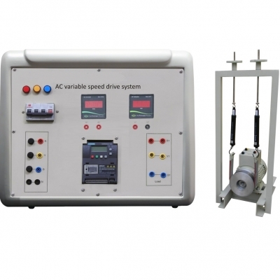
Gunn Diode Kit
Gunn Diode Kit Manufacturer, Exporter & Bulk Supplier from India for School Lab Equipment, TVET Tender & MOE Projects.
- Exported to 100+ Countries
- Made in India · Factory Direct
- MOE Tender & LC Payments Accepted
- For Schools, Colleges, TVET, Polytechnics
Product Description
Gunn Diode Kit is manufactured by Didactic Lab Equipments, a leading School Lab Equipment Manufacturer in India serving Ministry of Education tenders, vocational training centres, polytechnics and engineering colleges across 100+ countries. Buy Gunn Diode Kit at factory-direct prices with full technical support.
Technical Specification
and antennas used to broadcast information in microwave
field.
In detail, it is possible to analyze and test the following major
aspects related to microwaves and to their application in
communication systems.
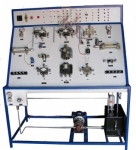
• Microwave generation with Gunn oscillator
• Waveguide Components and Antennas for microwaves
• Assembling and Measurements
This unit consists of a main Trainer and of a set of optional
waveguide Components (WG).
TRAINING PROGRAM:
• General microwave theory
• Characteristics of:
- Microwave components
- Waveguide and flange
- Horn antennas and parabolic reflector
- Reflection and polarization system
• Gunn Diode oscillator
• Gunn transceiver: Gunn oscillator and Schottky diode
• Measurement of direct frequency
• Wavelength measurement: in free space and WG
• Measurement of direct and reflected power
• Attenuation measurement
• Power division and impedance mismatching measurement
SWR and impedance matching
Measurement.
• Use of Smith’s chart for impedance calculation
• Impedance matching
• Signals separation in a transceiver system and transmitter
protection
• Directional couplers and T-hybrid
• Microwave antennas: gain and irradiation diagram
• Measurement of antenna gain:
- comparison method
- method of the two antennas
• Link attenuation
• Passive repeaters (mirrors)
• Doppler Radar with different antennas: it is possible to
observe the relationship between the object speed and the
received doppler signal
TECHNICAL SPECIFICATION:
• Gunn oscillator Frequency: 10525 MHz (X band)
• Gunn oscillator output power: +7 dB
• Waveguide internal sheath: silver-coated
• 2 waveguides – coaxial adapter
• 3 straight waveguides (WG)
• 1 WG slotted line
• 1 WG variable attenuator of 30 dB
• 2 WG fi xed attenuators of 3 dB and 6 dB
• 3 WG loading terminations:
- 2 matched 1W and
- 1 short-circuit
• 1 coaxial Detector:
- Input: +20 dBm (max), 50 , SMA, 10 – 12400 MHz
- Output: BNC, negative polarity
• 1 WG directional coupler:
- 3 ports, coupling 20 dB
• 3 WG horn antennas:
- Gain of 10 dB (n.2) and of 15 dB (n.1)
• 1 parabolic antenna:
- 0.36 m (diam.), 0.5 (f/D) and 29.5 dB (theoretical gain)
• 2 reflection planes:
- dimensions: 180x180 mm and 300x300 mm
• 1 polarization plane:
- dimensions. 180x180 mm
• 6 (high and low) supports and connection cables
• Rotary table with slider and graduated scale.
Power supply: 230 Vac 50 Hz single-phase - 20 VA
(Other voltage and frequency under request)
Bulk Tender Supply & Worldwide Export
- Bulk MOQ pricing for tenders & institutional orders
- Custom branding & private-label available
- CIF / FOB / Door-to-door delivery worldwide
- Letter of Credit, T/T, MOE tender payment terms
- Installation, commissioning & training support
- Manufacturer warranty & after-sales service
Related Lab Equipment
Why Buy Gunn Diode Kit from Didactic Lab Equipments?
As one of India's leading Didactic Lab Equipment Suppliers and School Lab Equipment Manufacturers, we supply Gunn Diode Kit in bulk for educational tenders, MOE projects, TVET training centres, polytechnics, engineering colleges and research universities worldwide. Our manufacturing facility in Ambala (Haryana, India) ships to 100+ countries with factory-direct pricing.
Looking for Gunn Diode Kit in bulk for school lab tenders, college lab supply or vocational training centres? Our team handles the complete tender cycle — technical specifications, pre-shipment inspection, FOB/CIF logistics and after-sales support. Request a customised quotation today.