- Civil Lab Mechanical Lab Engineering Lab Equipments
- sales@didacticlabequipments.com

CAT NO: DIDACTICNLE-Export-081053
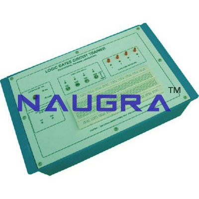
Logic Gates Circuit Trainer.
Logic gates circuit trainer offers a unique
entry into the world of microelectronics. The system combines simple,
easy to use, ICs for various gates and flip-flops, power supply, clock
input and output state with a versatile solderless bread board area.
Students new to digital electronics can implement logic circuits in
a matter of minutes on the bread board area. As confidence grows the
student will naturally progress for using more complex logic ICs on the
large bread board area. This unique approach enables the unit to be used
by the absolute beginner, yet it may also be usefully employed in
advanced project work. The many outstanding features of the logic
trainer, combined with its ease of use and robust housing, make it the
first choice for those wishing to introduce students to digital
electronics for the first time.
Practical experience on this board carries great educative value for science and engineering students.
Specifications:
OUTPUT D.C. VOLTAGE : Fixed 5V ±1% .
OUTPUTCURRENT : 1 Amp.
LOAD REGULATION : ±1% of the highest specified output voltage.(NO LOAD TO FULL LOAD)
LINE REGULATION (For ±10% change : less than 50 mV. in mains Voltage i.e. 230V)
RIPPLE AND NOISE : less than 5 mV.
CLOCK INPUT DEVICE : Clock pulse of 1 second.
DEBOUNCED LOGIC SWITCH (HI/LO) : Four nos. Input voltage of HI level ³ 2.25V. Input voltage of LO leve £ l 0.8V.
4 BITS LED OUTPUT INDICATOR : Maximum input voltage less than or equal to 5V D.C.
SOLDER
LESS BREAD BOARD : Bread Board having one main strip, total
interconnected 640 tie points for ICs and half main strip, total
interconnected 320 tie points for power supply, Clock, Input and output
state. Each strip having length 173mm and accepting dia 0.56mm/24SWG
recommended, use only 22-26 SWG wire for interconnections.
BASIC
LOGIC GATES & : Four AND gates, Four OR gates, Four NAND gates,
Four NOR gates, Six NOT FLIP FLOP UNITS gates, Dual J-K flip-flop, J.K.
master/slave flip-flop & Dual D-type flip flop.
APPLICATIONS
: Verification of AND, OR, NOT, NAND, NOR Gates & their truth
table. Verification of Boolean Algebra. The half-adder and full-adder
design. Verification of D-type flip-flop and truth table. Verification
of JK flip-flop and truth table. Verify cation of Dual JK Master/Slave
flip-flop and truth table.
Features:
The unit is operative on 230V ±10% at 50Hz A.C. Mains.
Strongly
supported by detailed Operating Instructions, giving details of
Object, Theory, Design procedures, Report Suggestions and Book
References.
Weight : 3 Kg. (Approx). Dimension : W 340 x H 110 x D 210
Optional Accessories :
Jumper wire bag (4 reels, 5M/reel),Cutter/Stripper tool.
