
Optical Fibres And Accessories Power Supply Unit Interactive Control Unit & Software
Optical Fibres And Accessories Power Supply Unit Interactive Control Unit & Software Manufacturer, Exporter & Bulk Supplier from India for School Lab Equipment, TVET Tender & MOE Projects.
- Exported to 100+ Countries
- Made in India · Factory Direct
- MOE Tender & LC Payments Accepted
- For Schools, Colleges, TVET, Polytechnics
Product Description
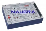
Optical Fibres And Accessories Power Supply Unit Interactive Control Unit & Software is manufactured by Didactic Lab Equipments, a leading School Lab Equipment Manufacturer in India serving Ministry of Education tenders, vocational training centres, polytechnics and engineering colleges across 100+ countries. Buy Optical Fibres And Accessories Power Supply Unit Interactive Control Unit & Software at factory-direct prices with full technical support.
Technical Specification
The trainer enables the study, with the help of the
theoretical-experimental handbooks, of the theoretical
concepts with tests, experimental measurements and trouble-
shooting operations on the following circuits and optical fiber
communication systems:
• Optical sources
• Optical detectors
• Optical fibers
• Analog and digital optical transmitter / receiver
• Electrical interfaces
• Signal sources
• Data coders and decoders
• TDM and Audio/Video multiplexer / demultiplexer
TRAINING PROGRAM
• Fiber characteristics: structure, propagation modes, numerical
opening, modal and chromatic dispersion, attenuation
and band
• Optical sources and detectors: Led and laser diodes, PIN
and avalanche photodiodes
• Optical connectors and coupling systems
• Led polarization and emitted optical power adjustment
• Digital and linear driving of the Led diode
• Responsivity of the photodetector
• Optical fiber attenuation
• Analog and digital communication systems
• Data coding/decoding: Manchester, Biphase Mark/Space
• Tx/Rx data with TDM multiplex
• Tx/Rx of FM analog signals
• Tx/Rx of video+audio signals
• Connection between PCs via RS232 interface
• Trouble-shooting
TECHNICAL SPECIFICATIONS
• Electrical interfaces: TTL, V24/RS232C, analog 1V-7MHz bw
• Signal sources: TTL generators, data (0/1/0&1/4x0&4x1) and
audio; microphone; 5 patterns video generator
• Data coders / decoders: NRZ, Manchester, biphase
Mark/Space
• 8-channel TDM data multiplexer / demultiplexer
• MPX A/V: audio modulator (FM 5.5MHz), A+V combiner
• Optical sources: LED at 660nm and 820nm
• Detectors: photodiode PIN 660nm and 820nm
• 5 optical cables: plastic fiber, 1.5m and 5m, 1000μm; glass
fiber, 3m, step-index, 200/230μm; glass fiber, 3m, gradedindex,
50/125μm; glass fiber, 3m, single-mode, 10/125μm
• Connection in plastic fiber ST/Snap-In
• ST-ST adapter
• Reception circuits: transimpedence amplifier, FM PLL
demodulator
• Video/audio demultiplexer: audio demodulator (FM 5.5 MHz),
video amplifier, audio amplifier 0.5W with loudspeaker
• 1-fault simulator
• Power supply: ±12Vdc
• Dimensions: 386x248x40 mm
INCLUDED ACCESSORIES
• Theoretical-experimental tests
• Cables as necessary and 6 different fiber cables
• Microphone, loudspeaker and ST-ST adapter
OPTIONAL ITEMS
• Practical Kit for connection and headings
• Optical source in I/II window
• Optical power meter in I/II/III windows
SOFTWARE
• Multimedia Educational Software
“TELECOMMUNICATIONS”
Bulk Tender Supply & Worldwide Export
- Bulk MOQ pricing for tenders & institutional orders
- Custom branding & private-label available
- CIF / FOB / Door-to-door delivery worldwide
- Letter of Credit, T/T, MOE tender payment terms
- Installation, commissioning & training support
- Manufacturer warranty & after-sales service
Related Lab Equipment
Why Buy Optical Fibres And Accessories Power Supply Unit Interactive Control Unit & Software from Didactic Lab Equipments?
As one of India's leading Didactic Lab Equipment Suppliers and School Lab Equipment Manufacturers, we supply Optical Fibres And Accessories Power Supply Unit Interactive Control Unit & Software in bulk for educational tenders, MOE projects, TVET training centres, polytechnics, engineering colleges and research universities worldwide. Our manufacturing facility in Ambala (Haryana, India) ships to 100+ countries with factory-direct pricing.
Looking for Optical Fibres And Accessories Power Supply Unit Interactive Control Unit & Software in bulk for school lab tenders, college lab supply or vocational training centres? Our team handles the complete tender cycle — technical specifications, pre-shipment inspection, FOB/CIF logistics and after-sales support. Request a customised quotation today.