
PCM Switching & Transmission Systems
PCM Switching & Transmission Systems Manufacturer, Exporter & Bulk Supplier from India for School Lab Equipment, TVET Tender & MOE Projects.
- Exported to 100+ Countries
- Made in India · Factory Direct
- MOE Tender & LC Payments Accepted
- For Schools, Colleges, TVET, Polytechnics
Product Description
PCM Switching & Transmission Systems is manufactured by Didactic Lab Equipments, a leading School Lab Equipment Manufacturer in India serving Ministry of Education tenders, vocational training centres, polytechnics and engineering colleges across 100+ countries. Buy PCM Switching & Transmission Systems at factory-direct prices with full technical support.
Technical Specification
the main issues concerning coding, switching and digital transmission of signals. The system carries out all the functions
of a branch exchange used for communications in a switched
PSTN (Public Switched Telephone Network) line.
TRAINING PROGRAM:
• Basics of telephony:
- telephone terminal
- transmission medium
- switching devices
• Telephone:
- acoustic/electrical transmission transducer
- electrical/acoustic reception transducer
- dial and electronic keyboard
- communication signals with the branch exchange
- TONE/PULSE calling tones
- power supply
• User interface (SLIC):
- B (Battery powered): telephone set powered by the branch
exchange
- O (Overvoltage protection): protection against overvoltages
from the line
- R (Ringing): control of ringing current
- S (Supervision): detection of the hook switch pulses or
multifrequency dialling tones
- H (Hybrid): conversion from 2 to 4 wires and vice versa
- T (Testing): signals level; characteristics on line
• CODEC:
- channel filter 300-3400 Hz in transmission and reception
- PCM coding and decoding at 64 kb/s with A-type or μ-type
compression
- Transmission and reception Time Slot assignment and
frame insertion at 2048 kb/s
• Simultaneous communication of more users:
- analog multiplex: FDM
- digital multiplex: TDM-PCM
- multiplex/demultiplex
- signal regenerators
- international standards
• Digital switched matrix:
- connection memory and data memory
- slot and frame switching
- frame switching
- display of frames and of input and output slots
• CEPT interface, artificial line and noise:
- synchronism and signaling bit insertion
- HDB3 coding of the signal to be transmitted
- HDB3 decoding of received signal
Line interface:
- E1/T1 line standard
- Line driver and impedance matching
- Attenuation and distortion due to the line
- Noise effects
- Reception equalizer
- Extraction of reception clock signal
- PRBS generation and detection
- Detecting transmission loss and received carrier
• Line signal conversion: unipolar-bipolar
• Artificial line simulator:
- Attenuation and noise
• Timing and exchange tones:
- bit, frame and time slot synchronism
- tone generation
• Simulation and troubleshooting
TECHNICAL SPECIFICATION:
• 4 telephone sets: PULSE/TONE dialling
• Operating modes:
- Local: TDM E1-32 frame generation, PCM channels and
digital exchange switching
- Local line: TDM E1-32 frame generation, PCM channels,
on line 4 transmission with HDB3 coding, Loop with Line
Simulator and digital exchange switching
- Testing line: like Local line with assessment of service
quality
- Remote Loop: like Local line with external Loop
- Remote Master/Slave: a bidirectional link can be established
to connect 2 Trainers
• Loop modes:
- Internal: with Line Simulator
- External: with output and input on coaxial line
• 4 User interfaces (SLIC) for the connection of 4 Users for
• POTS or PSTN networks:
- Compatibility: telephone, modem, fax
- Dialling: pulses, multifrequency tones (DTMF)
• 4 CODECs with functions of:
- Filter
- Signal conversion: analog/digital PCM
- Time-Slot assignment: transmission and reception
- Serial frame generation: 32 channels (2048 kb/s)
• 1 Digital Switch that “routes” the PCM signals for the required
links
• 1 CEPT Interface with functions of:
- HDB3 coder-transmitter
- HDB3 receiver-decoder
• 1 Line Interface with functions of:
- Line equalizer
- Reception clock regenerator
• 1 Simulator of artificial line:
- Controls of Attenuation and Noise generator
• 1 Control microprocessor interfaceabile with a PC
• 1 Synchronization system for displaying
• Time Slots on oscilloscope
• State indication LED:
- Signaling: Clock Loss, BER, Frame Sync, Multi-Frame Sync
- Incoming calls: for Users1, 2, 3 and 4
- Switch Hook detection: for Users 1, 2, 3 and 4
- DTMF binary code and Line signaling: for User1
• Fault simulator: 12 faults can be inserted via switches; this
unit is protected by key-locked cover
• Test points: 46 test points connected directly with the
circuits of the equipment
• 1 RS232 interface for connection with supervision PC
• 1 Supervision software for programming the operating
parameters of branch exchange: it must be installed on 1 PC
(not included)
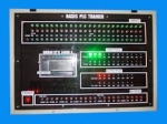
• Framework: compact box with liftable lid containing all
electronic parts, signaling and test points and fault simulator.
A block diagram of the circuit is available on the lid
Power supply: 230 Vac 50 Hz single-phase - 35 VA
(Other voltage and frequency under request)
Dimensions: 445 x 335 x 135 mm (closed)
Weight: 13 kg
Bulk Tender Supply & Worldwide Export
- Bulk MOQ pricing for tenders & institutional orders
- Custom branding & private-label available
- CIF / FOB / Door-to-door delivery worldwide
- Letter of Credit, T/T, MOE tender payment terms
- Installation, commissioning & training support
- Manufacturer warranty & after-sales service
Related Lab Equipment
Why Buy PCM Switching & Transmission Systems from Didactic Lab Equipments?
As one of India's leading Didactic Lab Equipment Suppliers and School Lab Equipment Manufacturers, we supply PCM Switching & Transmission Systems in bulk for educational tenders, MOE projects, TVET training centres, polytechnics, engineering colleges and research universities worldwide. Our manufacturing facility in Ambala (Haryana, India) ships to 100+ countries with factory-direct pricing.
Looking for PCM Switching & Transmission Systems in bulk for school lab tenders, college lab supply or vocational training centres? Our team handles the complete tender cycle — technical specifications, pre-shipment inspection, FOB/CIF logistics and after-sales support. Request a customised quotation today.