
Satellite Trainer
Satellite Trainer Manufacturer, Exporter & Bulk Supplier from India for School Lab Equipment, TVET Tender & MOE Projects.
- Exported to 100+ Countries
- Made in India · Factory Direct
- MOE Tender & LC Payments Accepted
- For Schools, Colleges, TVET, Polytechnics
Product Description
Satellite Trainer is manufactured by Didactic Lab Equipments, a leading School Lab Equipment Manufacturer in India serving Ministry of Education tenders, vocational training centres, polytechnics and engineering colleges across 100+ countries. Buy Satellite Trainer at factory-direct prices with full technical support.
Technical Specification
The Trainer is based on a modern and complete
satellite reception system, properly changed to improve the
learning experience on the design and realization of a reception
system, dealing also with repair and maintenance problems of
the plants including the satellite receiver.
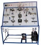
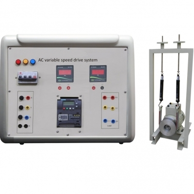
rainer consists of an external unit including: parabolic antenna,
driven positioner, polarizer and LNB converter; and of an indoor
unit mounted on the Edubox® structure, defining a compact
and functional set where you can find: the electronic circuits; a
detailed silk-screen panel with block diagrams; 38 test points
mounted on an easily accessible panel; the 24-fault simulator
and the theoretical-experimental tests.
(*): the trainer is configured according to the user’s needs.
TRAINING PROGRAM
• Direct TV signal broadcasting via satellite: orbital path,
geostationary satellites, emitted power, covering map,
transmission standard, coding systems
• Functional diagram of a reception plant for TV satellites
• Components characteristics: parabolic antenna, illuminator,
polarizer, LNB converter, motor-driven positioner, indoor unit,
positioner control
• Plant design
• Mounting and tracking of the parabolic antenna: “Azimuth-
Elevation” mounting and “Polar” mounting
• Motor-driven positioner regulation
• Mounting and regulation of the circular and linear (horizontal
and vertical) polarizer
• Mounting and tracking of the reception converter
• Tracking adjustment and memorization of satellite position
• Characteristics of the signal converted to intermediate
frequency
• Audio/video decoders operation: wave-form analysis
• Video decoder programming
• Audio decoder programming
• Trouble-shooting on different stages of the system
TECHNICAL SPECIFICATIONS
External unit:
• Parabolic Antenna: polar mounting, 1.2 to 3.7m diameter (*),
base mounted on self-holding structure
• Low noise converter
• Polarizer
• Positioner
• Cables: 50m for IF and control positioner and polarizer
• Dimensions: L= parabola diameter, H= 1m + parabola ray
Indoor unit:
• Receiver: IF input, outputs: video; audio; RF
• Antenna positioner control
• Structure: compact box with liftable cover with all the
electronic parts, the test points, the fault simulator; the cover
includes the block diagram of the circuit
• Fault simulator: 24 faults insertable by means of switches,
protected with key-locked cover
• Test points: 38 test points mounted on panel and directly
connected to the circuits of the equipment
• Power supply: 230Vac (110Vac upon request) – 50/60 Hz
• Dimensions: 130x420x430 mm (closed)
INCLUDED ACCESSORIES
• Theoretical-experimental tests
• Inclinometer, portable TV monitor, compass, power cord
• Power supply included into the structure
OPTIONAL ITEM
• Panoramic field meter with IF satellite extended band
SOFTWARE
• Multimedia Educational Software
“TELECOMMUNICATIONS”
Bulk Tender Supply & Worldwide Export
- Bulk MOQ pricing for tenders & institutional orders
- Custom branding & private-label available
- CIF / FOB / Door-to-door delivery worldwide
- Letter of Credit, T/T, MOE tender payment terms
- Installation, commissioning & training support
- Manufacturer warranty & after-sales service
Related Lab Equipment
Why Buy Satellite Trainer from Didactic Lab Equipments?
As one of India's leading Didactic Lab Equipment Suppliers and School Lab Equipment Manufacturers, we supply Satellite Trainer in bulk for educational tenders, MOE projects, TVET training centres, polytechnics, engineering colleges and research universities worldwide. Our manufacturing facility in Ambala (Haryana, India) ships to 100+ countries with factory-direct pricing.
Looking for Satellite Trainer in bulk for school lab tenders, college lab supply or vocational training centres? Our team handles the complete tender cycle — technical specifications, pre-shipment inspection, FOB/CIF logistics and after-sales support. Request a customised quotation today.