
Training Equipment in Industrial Hydraulics
Training Equipment in Industrial Hydraulics Manufacturer, Exporter & Bulk Supplier from India for School Lab Equipment, TVET Tender & MOE Projects.
- Exported to 100+ Countries
- Made in India · Factory Direct
- MOE Tender & LC Payments Accepted
- For Schools, Colleges, TVET, Polytechnics
Product Description
Training Equipment in Industrial Hydraulics is manufactured by Didactic Lab Equipments, a leading School Lab Equipment Manufacturer in India serving Ministry of Education tenders, vocational training centres, polytechnics and engineering colleges across 100+ countries. Buy Training Equipment in Industrial Hydraulics at factory-direct prices with full technical support.
Technical Specification
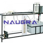
Approx. dim: 1410mm(L) x 750mm(W) x 1520(H).
The trolley must have two (2) lockable equipment storage cabinets, each consists of five (5) drawers (depths are 1 x 66mm, 2 x 85mm, 1 x 130mm, 1 x 200mm †approx. sizes). Cabinets and all drawers are to be steel, powder coated construction including drawer fronts.
The trolley must have two (2) circuit building plugboards (approx. size) 1100mm x 700mm, each with mounting holes must be fitted with rubber component retaining grommets, but also fitted with receptacle for 1/4 turn aircraft fasteners to lock hydraulic components onto plugboard (for safety).
The boards must be powder coated 16swg steel (at least).
Two (2) hydraulic power packs must be included, each being totally independent and can be used without interfering with the opposite side of the trolley.
Each power pack must have its own electric motor, pressure relief valve, return line filter, electrical start/stop control, oil level sight gauge, filler/breather, drain port, reservoir capacity 10 litres usable (each), flow 3,5 litres per min @ 65 bar. Electric motor must be overload protected with automatic trip (resetable).
Pressure and Tank manifolds must be plugboard mounted, with test points for use with pressure gauges.
The trolley is mounted on four (4) heavy duty, rubber tyred castors two (2) of which are swivel and lockable.
All hydraulic components and hoses must be fitted with genuine leakage free, 'flatâ€face', quickâ€connect, selfâ€seal couplings (male on valves, female on hoses).
Except for inâ€line components all components must be fitted on plugâ€in baseplate with 1/4 turn locking fastener.
All components must be genuine industrial components, used in/by industry.
Directional control valves must be mini 3 with 3mm nominal bore, rated at 315 bar with 12 litres per min flow.
Pressure control valves are series '0' with manual (knob) adjustment Set of Components †Hydraulics, comprises (all components must be identified by ISO1219â€1 symbols):â€
1 x Pressure Relief Valve
3 x Pressure Gauge with Test Point Adaptor †50mm diameter stainless steel casing. [
1 x Flowmeter, 0 †8 L/min (0,2 †2,0 US gal/min)
1 x Double Acting Cylinder 25mm bore x 200mm stroke (horizontal fitment) †with striker cam, must have 2 connections and miniâ€mess test point on each port [18] 1 x 4/2 way Lever / Detent Valve
1 x 4/3 way Lever / Detent Valve (Recirculating mid position)
1 x Shutâ€off Valve with Graduated Scale
2 x Oneâ€way Flow Control (Throttle/Check) Valves
1 x 3â€way Pressure Reducing Valve
1 x Pilot Operated (Ventable) 2â€stage, Pressure Relief valve
1 x Biâ€directional Motor †with 60mm diameter aluminium faceplate
3 x Cross Tee with Test Point
1 x Set of Hydraulic Hoses with Quickâ€connect couplings †(six (6) @ 650mm, four (4) @ 800mm, four (4) @ 1,000mm, two (2) @ 1,200mm)
1 x Double Acting Cylinder 25mm bore x 200mm stroke (vertical fitment) †with striker cam, must have miniâ€mess test point on each port.
1 x 20Kg weight for use with vertical cylinder
1 x 4/3 way Lever / Detent valve, (Closed mid position)
1 x 3/2 way Roller / Spring valve
1 x 2â€way Flow Control Valve, Pressure Compensated
1 x Check Valve
1 x Pilot Operated Check Valve
1 x Pressure Relief / Pressure Sequence Valve
1 x Accumulator Module with safety Circuit (built from separate components to show the system components and function)
Bulk Tender Supply & Worldwide Export
- Bulk MOQ pricing for tenders & institutional orders
- Custom branding & private-label available
- CIF / FOB / Door-to-door delivery worldwide
- Letter of Credit, T/T, MOE tender payment terms
- Installation, commissioning & training support
- Manufacturer warranty & after-sales service
Related Lab Equipment
Why Buy Training Equipment in Industrial Hydraulics from Didactic Lab Equipments?
As one of India's leading Didactic Lab Equipment Suppliers and School Lab Equipment Manufacturers, we supply Training Equipment in Industrial Hydraulics in bulk for educational tenders, MOE projects, TVET training centres, polytechnics, engineering colleges and research universities worldwide. Our manufacturing facility in Ambala (Haryana, India) ships to 100+ countries with factory-direct pricing.
Looking for Training Equipment in Industrial Hydraulics in bulk for school lab tenders, college lab supply or vocational training centres? Our team handles the complete tender cycle — technical specifications, pre-shipment inspection, FOB/CIF logistics and after-sales support. Request a customised quotation today.