
Back And Forth Motion System
Back And Forth Motion System Manufacturer, Exporter & Bulk Supplier from India for School Lab Equipment, TVET Tender & MOE Projects.
- Exported to 100+ Countries
- Made in India · Factory Direct
- MOE Tender & LC Payments Accepted
- For Schools, Colleges, TVET, Polytechnics
Product Description
Back And Forth Motion System is manufactured by Didactic Lab Equipments, a leading School Lab Equipment Manufacturer in India serving Ministry of Education tenders, vocational training centres, polytechnics and engineering colleges across 100+ countries. Buy Back And Forth Motion System at factory-direct prices with full technical support.
Technical Specification
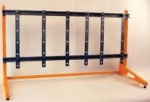
Back And Forth Motion System
This system use a back and
forth motion case UHING, mechanism which transforms the continuous
rotation motion of a smooth shaft in a linear back and forth motion.
Cinematically, it is like a screw-nut system. However two supplementary
functionalities can be achieved : the setting of the thread of the
screw-nut system and the change of the thread direction (helix on the
left or on the right). This last functionality allows to change the
displacement direction of the case. Otherwise, thanks to a special
feature, the inversion of the translation direction of the case is
almost instantaneous.
These
mechanisms are used a lot in the winding techniques. They are used to
distribute correctly the wires or the cables on a bobbin. Technically,
for this operation, it is important to check:
The reversing speed which conditions the quality of the winding .
The non sliding between the interior
rings of the bearings considering as the nut and the shaft whatever is
the acceleration of the case.
The non sliding during the loading of the case
Teaching objectives
This system allows to make practical works in the fields of the
Mechanical engineering and electrical engineering:
This system has a high-level
mechanical aspect because of the complexity of the reversing and
setting thread motion transformation case. It allows to study the
functional analysis of the different functions:
To measure the performances of the system (thread setting, transmissible
effort before sliding.
To cinematically model the UHING system (contact shaft – bearing ring,
thread setting system.
To make a computer simulation (SolidWorks) in relation to the thread
setting and direction change subsystems.
The electrical and control aspects are also very
important with the Direct Current motor and its 4 quadrants speed
driver, the instrumentation (speed, position and force sensors).
Practical works list:
Discovery of the system and internal functional analysis.
Experimental verification of the performances.
Kinematics’ computer simulation
Computer simulation of the thread setting
Computer simulation of the direction change
Measurement of the performances. Reversing time and thread
Study and measurement of the sliding.
Implementation of a winding operation. Associated setting
Closed loop control. Identification of the system
Quadrants functioning of the speed driver
Technical specifications
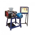
A testing bench including
A USING case mounted on support with device to
implement a winding operation. Two bobbins allow to adjust the device
and to achieve this operation with wires of different diameters
A direct current motor
Some sensors allow to measure in real time:
The rotational speed of the motor by a tachometer
The speed of transfer of the case by a tachogenerator
The motor current, picture of the torque
The angular
position of the bearing axis similar to a nut according to the time
during the reversing time by a potentiometer sensor.
A force sensor allowing to test limits sliding force.
A control cabinet including:
A 4 quadrants electronic
speed driver. The input set points imposed to the motor by the speed
driver are of the type :step, ramp and sinusoid speed.
A data acquisition card National Instruments allow to reach a frequency
of 10 000 Hz.
This level of measurement allows to study the reversing phase which last
about 0,1 second.
A digital transmitter for the rotational speed of the motor.
A switch for working in manual or software mode.
A control and data acquisition software
Using case for manipulation.
Case with cover made of Plexiglas® allowing the visualization of the
mechanical functioning of the system (setting of the thread and change
of direction)
Mechanical Testing Lab equipment manufacturers,exporters and Mechanical Testing Lab suppliers
Bulk Tender Supply & Worldwide Export
- Bulk MOQ pricing for tenders & institutional orders
- Custom branding & private-label available
- CIF / FOB / Door-to-door delivery worldwide
- Letter of Credit, T/T, MOE tender payment terms
- Installation, commissioning & training support
- Manufacturer warranty & after-sales service
Related Lab Equipment

Why Buy Back And Forth Motion System from Didactic Lab Equipments?
As one of India's leading Didactic Lab Equipment Suppliers and School Lab Equipment Manufacturers, we supply Back And Forth Motion System in bulk for educational tenders, MOE projects, TVET training centres, polytechnics, engineering colleges and research universities worldwide. Our manufacturing facility in Ambala (Haryana, India) ships to 100+ countries with factory-direct pricing.
Looking for Back And Forth Motion System in bulk for school lab tenders, college lab supply or vocational training centres? Our team handles the complete tender cycle — technical specifications, pre-shipment inspection, FOB/CIF logistics and after-sales support. Request a customised quotation today.