
A Multiplex line 671.00
A Multiplex line 671.00 Manufacturer, Exporter & Bulk Supplier from India for School Lab Equipment, TVET Tender & MOE Projects.
- Exported to 100+ Countries
- Made in India · Factory Direct
- MOE Tender & LC Payments Accepted
- For Schools, Colleges, TVET, Polytechnics
Product Description
A Multiplex line 671.00 is manufactured by Didactic Lab Equipments, a leading School Lab Equipment Manufacturer in India serving Ministry of Education tenders, vocational training centres, polytechnics and engineering colleges across 100+ countries. Buy A Multiplex line 671.00 at factory-direct prices with full technical support.
Technical Specification
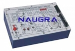
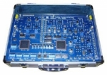
Interactive Practical Electronics System – I.P.E.S.
It consists of a set of components and circuits for performing experiments.
The lessons included in this module can be developed in:
- Standard mode: using the switches of the equipment and
consulting the handbook;
- Computerized mode: the interactive software version of
the handbook - interfaced to the module
via Control Unit , is used. This software inserts circuit
variations and faults automatically enabling the development
of lessons even without teacher’s assistance
TRAINING PROGRAM:
• 4-channel PCM/TDM transmission system
• Construction of PCM frame
• Transmission of 64 Kb/s through voice channel
• Operation of AMI/HDB3/CMI coders
• Transmission and reception circuits
• Characteristics of the transmission channel and noise
• Line equalization and ALBO circuit
• Clock recovery
• AMI/HDB3/CMI decoders
• Recovery of the frame synchronism
• Time switching of PCM channels
• Noise effect and error rate measurements
• Eye diagram
• Multi-channel PCM connections, with simultaneous
voice and data transmission
• Error rate measurement
• PC connection by means of RS232C interface
• Interconnection between 2 Personal Computers
using 2 experiment boards
TECHNICAL SPECIFICATION:
• Frame type: 5 time slots, 4 for voice and 1 for synchronism
• Tx/Rx time slot assignment: programmable
• Frame duration: 125 μs
• Time slot duration: 25 μs
• Data stream through voice channel: 64 Kb/s
• Data interface: TTL and V24/RS232C
• Line coders: AMI (Alternate Mark Inversion), HDB3 (High
Density Bipolar) and CMI (Coded Mark Inversion)
• Error detector for AMI/HDB3 code violation
• Data patterns: 320-64Kb/s; 0/1; 1/0 and 4x1/4x0;
64-bit pseudo-random
• Bit error meter with digital display
• Channel simulator: attenuation, passband and variable
noise
boards and 2 computers.
• Sine wave generators: synchronous 0.5/1/1.5/2 kHz
with timers
• Microphone and loudspeaker included
• Fault simulation: Possibility to insert 8 faults
• Test and interconnection points, Ø 2 mm
• Rapid modifications to circuits using jumpers
• 37-pin connector to the fault insertion unit
• 8-wire connector to the power supply unit
• Printed circuit board with protective treatment and mimic
diagram
• Module equipped with ABS protection on its lower side
Bulk Tender Supply & Worldwide Export
- Bulk MOQ pricing for tenders & institutional orders
- Custom branding & private-label available
- CIF / FOB / Door-to-door delivery worldwide
- Letter of Credit, T/T, MOE tender payment terms
- Installation, commissioning & training support
- Manufacturer warranty & after-sales service
Related Lab Equipment
Why Buy A Multiplex line 671.00 from Didactic Lab Equipments?
As one of India's leading Didactic Lab Equipment Suppliers and School Lab Equipment Manufacturers, we supply A Multiplex line 671.00 in bulk for educational tenders, MOE projects, TVET training centres, polytechnics, engineering colleges and research universities worldwide. Our manufacturing facility in Ambala (Haryana, India) ships to 100+ countries with factory-direct pricing.
Looking for A Multiplex line 671.00 in bulk for school lab tenders, college lab supply or vocational training centres? Our team handles the complete tender cycle — technical specifications, pre-shipment inspection, FOB/CIF logistics and after-sales support. Request a customised quotation today.