
Maxwell S Pendulum
Maxwell S Pendulum Manufacturer, Exporter & Bulk Supplier from India for School Lab Equipment, TVET Tender & MOE Projects.
- Exported to 100+ Countries
- Made in India · Factory Direct
- MOE Tender & LC Payments Accepted
- For Schools, Colleges, TVET, Polytechnics
Product Description
Maxwell S Pendulum is manufactured by Didactic Lab Equipments, a leading School Lab Equipment Manufacturer in India serving Ministry of Education tenders, vocational training centres, polytechnics and engineering colleges across 100+ countries. Buy Maxwell S Pendulum at factory-direct prices with full technical support.
Technical Specification
The mechanical energy of a system is the result of the sum of kinetic and potential energies.
When there are only conservative forces, the principle stating that “during transformation, partial energies are transformed, whereas mechanical energy is preserved” is valid.
Maxwell’s pendulum is a very good example of the principle of conservation of mechanical energy.
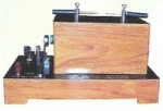
The system consists of a flywheel.
Two wires are wound around the flywheel axis in the same direction, whereas the opposite ends are connected with a horizontal support.
Winding the wires around the axis will load the flywheel so that it will reach a certain height from the reference plane. When released, the flywheel starts to go down gathering speed.
When arrived at the lowest point allowed by unwinding wires, pendulum will rewind in the opposite direction and starts going upwards again.
In ideal conditions it would come back to the same starting height ; however motion is damped by frictions with wires and with the medium (air) and after a certain number of oscillations, pendulum will stop in the lowest point allowed by wires.
The principle of conservation of energy is used to determine pendulum’s period, that is the time spent by the flywheel in going down and up : the variations of kinetic energy of both translation and rotation will compensate the variations of potential energy.
All the energy is potential at the maximum height, whereas all the energy available at the lowest point is kinetic.
That could continue ad infinitum, in an ideal system, but actually the wheel will stop at a certain point because of friction.
Pendulum consists of a thin metallic disk with a hole in its centre where a shaft, fixed to the disk with a screw, is inserted.
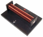
The shaft is a metallic bar turned and drilled to realize Maxwell’s pendulum with different values of R/r ratio.
The two wires supporting the pendulum are run through two thin crosswise holes drilled at the ends of each section.
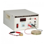
The system must also be equipped with two sensors (a force sensor and distance sensor) that are interfaced to datalogger and to PC for the study of system kinematics and dynamics.
Pendulum hooks on to the force sensor via a pair of parallel wires tied to pendulum ends on the main axis.
Values of R/r depend on the pair of holes being used.
The position sensor is arranged at the base of the system and it enables to assess the speed with which the wheel arrives at the end of its travel, using sonar technique.
The system used in this equipment is characterized by a high frequency of data acquisition and by a versatile dataprocessing software enabling to study not only the up and down movement of pendulum, but also the phase of collision with the wire end, besides checking the equality between impulse of the force applied by the wire to the pendulum and the variation of pendulum momentum, in an experimental way.
TRAINING PROGRAM
Conservation and dissipation of mechanical energy
Translation energy versus time
Rotation energy versus time
Potential energy versus time
Variation of momentum
Moment of inertia
Angular velocity
Angular acceleration
Instantaneous speed
Weight of pendulum in static and dynamic conditions
Impulse-momentum theorem
Calculating the period of pendulum COMPONENTS
1 supporting base
2 vertical rods for mounting the wheel
2 horizontal rods for supporting the wheel and the force sensor
1 wheel with pin of different radii
String
4 terminals
Physics Workshop Laboratory Supplies Maxwell S Pendulum Manufacturer,Supplier and Maxwell S Pendulum Exporter in India
Bulk Tender Supply & Worldwide Export
- Bulk MOQ pricing for tenders & institutional orders
- Custom branding & private-label available
- CIF / FOB / Door-to-door delivery worldwide
- Letter of Credit, T/T, MOE tender payment terms
- Installation, commissioning & training support
- Manufacturer warranty & after-sales service
Related Lab Equipment


Why Buy Maxwell S Pendulum from Didactic Lab Equipments?
As one of India's leading Didactic Lab Equipment Suppliers and School Lab Equipment Manufacturers, we supply Maxwell S Pendulum in bulk for educational tenders, MOE projects, TVET training centres, polytechnics, engineering colleges and research universities worldwide. Our manufacturing facility in Ambala (Haryana, India) ships to 100+ countries with factory-direct pricing.
Looking for Maxwell S Pendulum in bulk for school lab tenders, college lab supply or vocational training centres? Our team handles the complete tender cycle — technical specifications, pre-shipment inspection, FOB/CIF logistics and after-sales support. Request a customised quotation today.